
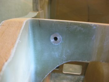
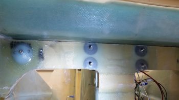
I started today by filing down & sanding the right CNL bushing that holds in the AN4 bolt for the right canard lift tab. It was sticking out about 0.030″ past the surface of the F22 glass so I wanted to level it with that glass. It took about 20 minutes, but I finally got it.
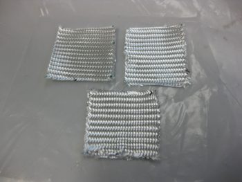
I measured the lift tabs on the canard to get the measurement for the BID pad that needed to go under the left side canard lift tab. I cut 6 squares approximately 2″ x 2″ and then stacked them in sets of 2 for prepregging.
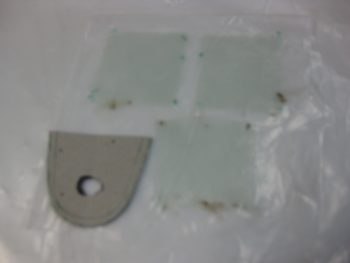
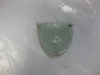
I then made up a template to use for cutting out the BID pads for the general shape of the lift tab, and to also mark where a hole needed to be made for the bolt to pass through. I was originally thinking I might clamp the lift tab in place then drill the 1/4″ hole after it cured, but that was most likely problematic with a nutplate sitting in the way … Uh, hmmmm. Maybe just a tad easier to start out with the bolt hole in place and then use the AN4 bolt as the clamp, since then it would be set at exactly the right place anyway! (Sorry for the blurry pic…)
After wetting out the BID, I then used my template and marked up the 3 sets of 2-ply BID squares.
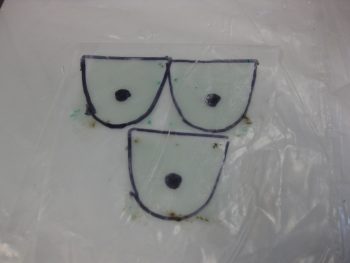
I then cut them out.
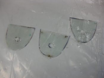
And combined them to make one big prepreg set with 6 plies of BID.
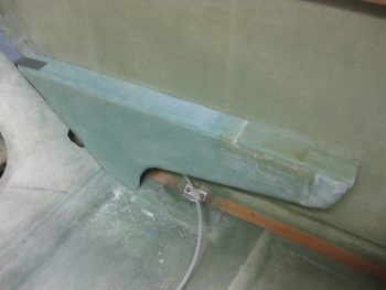
I then laid up that BID on the left side canard mount CNL embedded in F22.
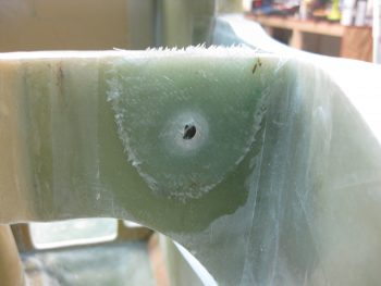
I added a bit of flox just to smooth it all out while the tab was under compression.
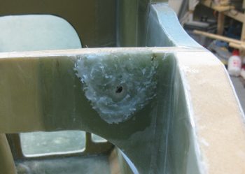
For the right side I merely added a bit of flox to take up any gap there might be.
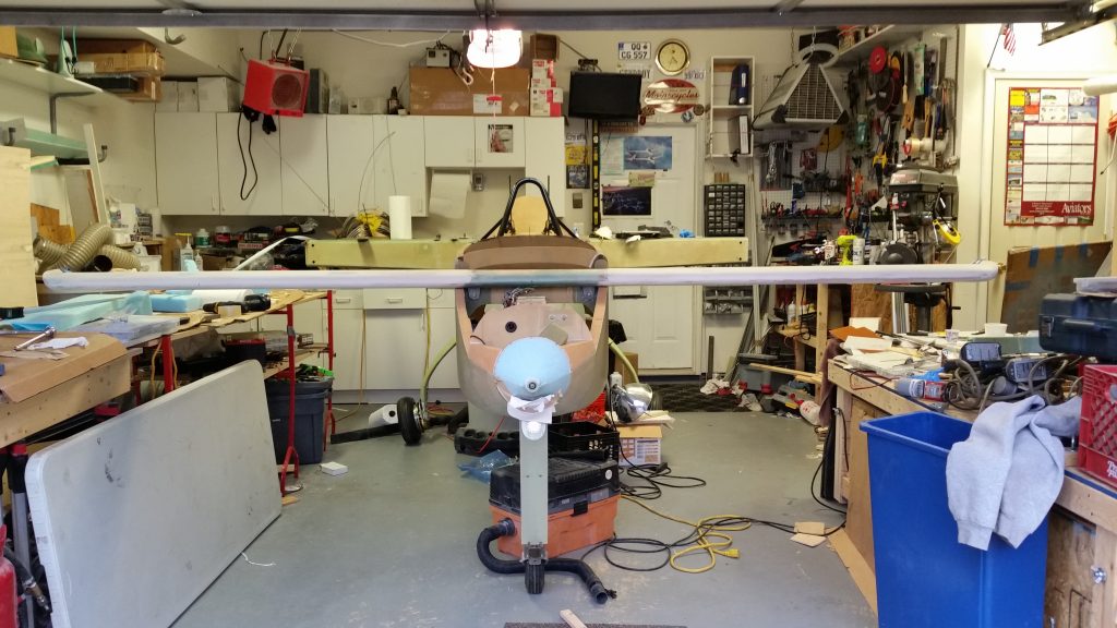
I then mounted the canard & bolted it in place. I measured the canard from the CS spar CL to each canard tip and then from each end of the CS spar to the each canard tip as well. I was incredibly relieved that all the numbers were close to perfect. Moreover, when I lined up on the extended CL of the fuselage, you can see in the pic below that the canard is about as perfectly aligned in relation to the CS spar as you can get. And if the canard is lined up nicely on the spar, it should line up very well with the wings as well!
[Note: This is one reason I had planned to mount the canard when I did, to allow for getting out front and ensuring it was aligned…. I just didn’t account for having only 2 feet in front of the nose as I did on the side of my house. So this is the first time I’ve got to step back and look at my mounted canard from the front & at a good distance.]
While the BID & flox pads under the canard lift tabs were curing, I marked the left GIB armrest to cut it at 2.1″ wide on each end (stock is 1.9″).
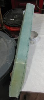
I then did the cut-fit-sand cycle for about 8-10 times before dialing in the fit of the left GIB armrest.
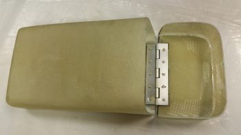
With the left GIB armrest good to go, and the BID on the canard mount still curing, I went ahead & mounted the hinge for the nose tool box in place, with 5 rivets each side.
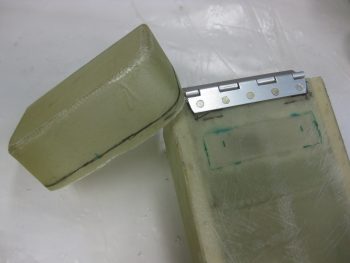
Here’s a shot of the hinge mounted to the lower “box” side of the tool box.
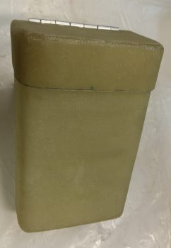
I of course needed to trim down the tool box lid, which I did.
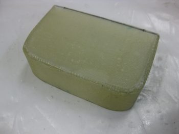
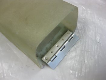
Once the lid was trimmed, I then riveted it to the hinge that was mounted to the tool box. Below pics are shots of the aft and front sides of the tool box lid hinge.
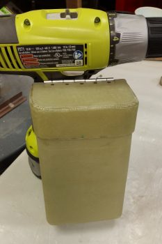
And here’s two “Action Poses” . . . ha!
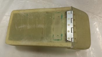
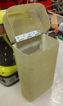
Finally, here’s a shot that shows a good portrayal of how it will look in the nose when opened for access.
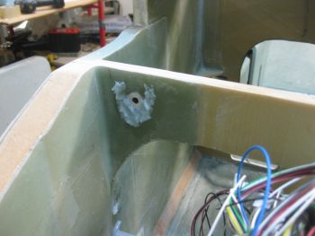
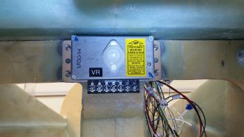
Finally . . . I was having a text discussion with Marco and sent him the pic below. Now, since I had to remove a bunch of F22 material on the top to level out the front edge, it never dawned on me that I might make it impossible to mount the voltage regulator . . . if the bottom of the canard was too close to the top F22 edge and prevented me from mounting the Voltage Regulator.
I went upstairs and grabbed the Voltage Regulator and then put it in place. It slid right in with no haggling. Yay!
Tomorrow will be a light build day, but I will continue to work on the canard & elevators to finalize both those installs.
I should come up there so that you can position armrests, backrest, headrest, etc. to my liking. LOL.
Sounds like a swell idea! Come on up! :)