
I started out today with a number of small layups and epoxy related tasks. So in lieu of my normal chronological discussion, I’m going to present stuff here by topic. Moreover, these are all tasks that I consider prerequisites to the strake build… just to be clear that I’m not going off-topic regarding the strake build. My plan was to get the outboard ribs installed and then get all these prerequisites knocked out.
First up. I decided to use a small piece of Kevlar as the final ply on the oil heat line protective sleeve. I laid it up and then peel plied and set it aside to cure.
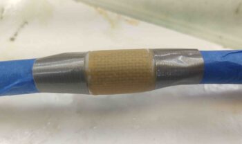
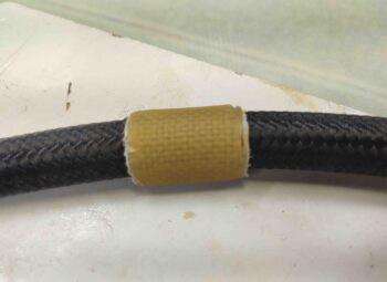
A few hours later I pulled the peel ply and rough razor trimmed the edges. I’ll clean it up a bit more when I get ready to install it in the plane. The plan is to install the oil lines first, then slide this sleeve in place. When it’s in the correct position, I’ll add some flox and a couple small securing plies of BID on each side.
The second small task was floxing in a stainless steel 90º angled bracket with an eyelet for attaching a retract spring on the nose hatch latch. This spring will pull the cable release handle back closed to reset it to allow the hatch to be closed and locked.
Without the spring pulling the cable back into an “armed” position the latch’s lever arm is caught in a “half-cocked” state, preventing the latch from closing and locking all the way when the hatch door is closed. I’ve been manually manipulating this sequence but clearly that would be problematic in the future… and of course I want the operation to be as hassle free as possible.
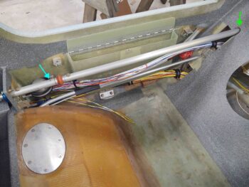
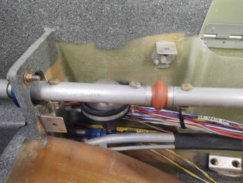
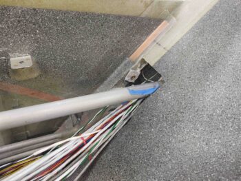
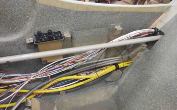
I then got to work on yet another task that has needed to be completed for a long, long time now. I installed the aft aileron control tube (CS121) with attached universal joint (CS120) to the existing control tube interconnecting piece (CS116). The blue arrow is pointing at the pilot hole I drilled for the securing AN3-11A bolt (per plans).
The green arrow at the aft end of the tube is pointing at the notch I spent a good half hour plus in creating in the seat back for the tube to align correctly with firewall mounted control tube bearing.
If you’re wondering why my aileron control tube is positioned higher than the aft corner of the armrest, it’s all about 2nd and 3rd order affects involved with modifications. I’ll remind everyone that my pilot seat bulkhead is 1.4″ wider than per plans. My back seat is about 0.8″ wider than plans. However, my firewall is plans width. So although the waterlines and fuselage stations of these installed components are per plans, the curvature of my fuselage combined with the use of the Cozy Girrrl control stick brackets mandated some finagling of the left/right (butt line) install positions.
Bottom line is that all the fuselage width mods, etc. made for some interesting downstream configuration challenges… this being one them.
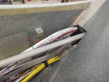
Here we have the aft control tube installation complete and finally bolted into place after these many years.
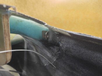
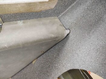
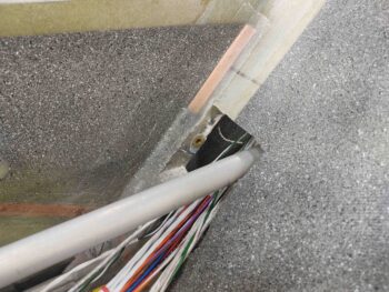
Now, back to the “sins” of the past and the current impact to my back seat left armrest. As you can see, with the aileron control tube entering the back seat at a point higher than the armrest top, it causes the armrest to rest upon the actual control tube. No muy bien.
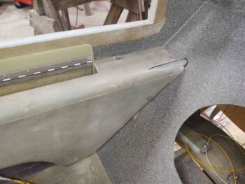
To remedy the armrest vs. control tube clearance issue, I spent nearly an hour slowly trimming back the inboard aft corner of armrest to create a stretched oval-type notch to ensure the control tube could rotate freely and unhindered.
As an aside, I’d like to note that the white & yellow wires sitting just inside the hell hole, resting on the gear bow, are newly run wires for the fuel tank probe control heads. I had to move the control head modules down into the hell hole since there was no space to mount them in the D-Deck/GIB headrest. Earlier today I terminated much longer wires with D-Sub sockets, popped them into the GRT EIS D-Sub connector and then ran them down into the hellhole. Conversely, I ran a pair of wires for the oil cooler louver actuator wires up from the hell hole into the D-Deck and then out the back through the firewall into the engine compartment.
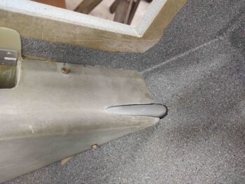
With a closer view you can see the clearance created in the armrest around the control tube.
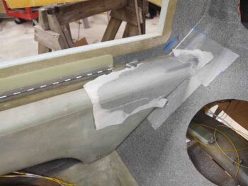
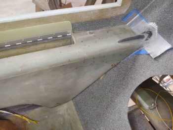
After applying protective tape to the aileron control tube and surround GIB seat back, I then made a paper template out of a sheet of printer paper that allowed me to cut out 4 concentric plies of BID to cover the exposed control tube, while still maintaining good clearance.
I laid up the 4 plies of BID and then peel plied the layup.
Jumping back in time to earlier in the day: I drilled a hole in the upper outboard control tube through-hole in the pilot seatback to flox a RivNut in place. This RivNut is a hard point for a wire-securing Adel clamp.
Here’s the bolt and tape-covered washer removed, and the excess flox cleaned up a bit.
And an “action shot” of the Adel clamp in place, securing the top bundle of wires.
Here’s a shot of the front seat right sidewall, with the intercom temporarily in place, to assess cable/wire management requirements. Over the next few days I’ll be adding a click bond or two, another RivNut hardpoint and most likely a composite “bridge” to detour the top wire bundle around the intercom.
Finally, after a few hours I pulled the peel ply and some tape off the back seat armrest layup. It needs a bit of sanding, and of course a trim, but overall I’m really pleased with the outcome.
Tomorrow I’ll finish cleaning up and trimming the armrest layup, and if the weather forecast holds I should be able to prime and paint it.