
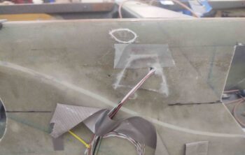
I started out today by pulling the GIB right armrest away from and off the protective tape. With the tape removed, I then set it back in place and marked the glass trim line.
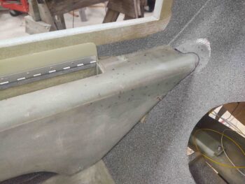
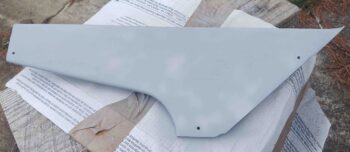
A few iterations later I had a final trimmed product. I also sanded and prepped the armrest for primer and paint.
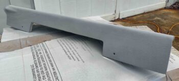
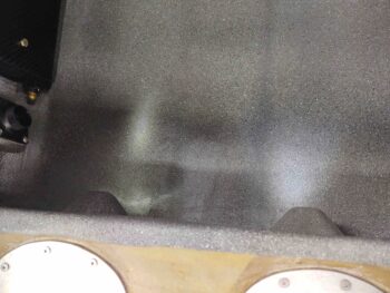
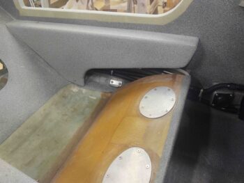
Here’s another shot of the new aft area configuration of the GIB right armrest.
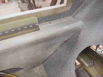
I then took the armrest outside and primed it.
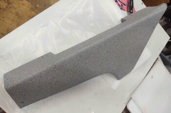
A bit later I hit it with a couple of coats of my gray granite paint. This shot is actually about 4 hours later after I brought it back into the shop from outside.
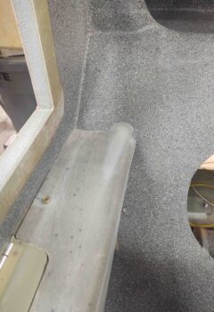
And even a few hours later after the shot above, I set the armrest back in its place. I’ll clear coat this armrest on the next good weather day.
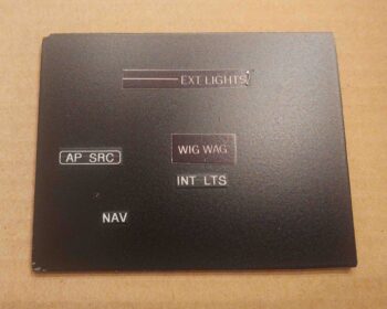
Speaking of clear coating. Since I was outside painting the armrest above anyway, I quickly printed off some new labels and applied them to my painted aluminum test piece. I then clear coated the glossy labels and this is the result I got:
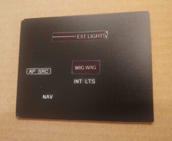
Not bad at all in my opinion. I tried to get 2 contrasting shots as far the light hitting it to show what you can see as far the edges. Yes, you can see an edge when the light hits it at a certain angle, but in my opinion it looks pretty darn good. Actually, another coat or two of clear would soften the edges even more.
Yep, I think this dog will hunt! (i.e. I’m pressing forward with this solution)
With a “win” in hand I then had to face a big oops I made when I installed the GIB right sub-panel. I think my oversight was a combination of trying to get it done quickly (always!), unlabeled wires, my wiring diagram not being clear enough, and bad assumptions (that I had finished the wiring) on my part.
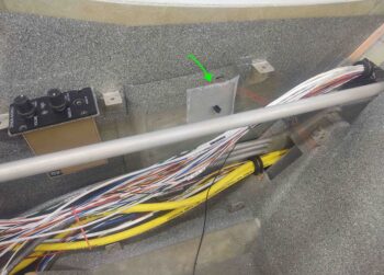
The bottom line though is that as I was running all the wires along the fuselage side wall I discovered the white and red control wires for the GIB floor LEDs. The color of the GIB map and floor lights is controlled by the upper Up/Down switch, whereas the ON switch is a rotary switch with the first position (shown below) OFF. The 2nd position (10 O’clock) is the floor lights. The 3rd position (12 O’clock) is the map light. And the last position is BOTH floor and map.
If the floor lights didn’t constitute half of the rotary ON/OFF switch, I would just leave them disconnected. But to have a rotary switch with half the positions doing nothing, and the end result being: OFF-(NOTHING)-MAP-MAP… it just doesn’t fly in my book. So I had to fix it.
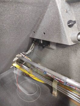
However, I wasn’t about to ‘go nuclear’ and do a massive cut out, replace and cosmetic surgery after the fact by removing the sub-panel. What I did have available to me though, this being still in the pre-strake phase, was the external wall in between the 2 right side strake fuselage openings.
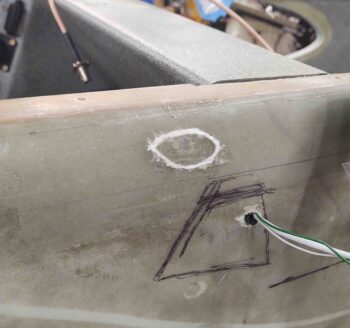
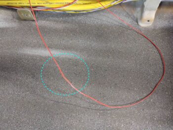
After some calibrated eye-balling, I marked the cut lines… the goal was to get as big a hole as possible to get access for my soldering iron to fit and get the 2 stray wires attached.
My first task was to extend the length of the red wire by solder splicing another length of 22 AWG red wire to the existing one.
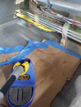
After splicing on a new wire, I covered the solder joint with some red heat shrink.
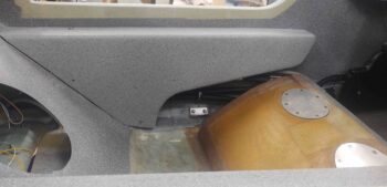
After spending about 15 minutes running the wires up to the outboard side wall opening, I then spent a good 20 minutes carefully cutting my switch access hole.
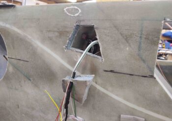
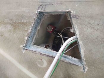
Here’s a closer shot.
Oh, by the way… to make sure I really made it a challenge, I even misread the helpful labels I had put on the top and bottom of the switch (which were meant for wire position, not switch position since they are opposite. e.g red light is down but the wire goes on top on the back of the switch) and I actually installed the switch upside down. Not a big deal for actual wiring since I just swapped the position numbers and put the wires how I wanted the switch to work (again, red down and white up). The increased difficulty with the switch installed upside down is that it put the tiny solder lugs on the inboard side of the switch, and behind the other wires for the bottom lug.
Well, I worked the issue and tested out the lights before soldering the red wire to the top switch lug.
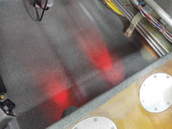
And then did the same for the white wire on the bottom switch lug.
After one last final check, I buttoned up the hole with the removed piece using micro and a ply of BID over each cut line. I took this pic a bit later after I finished the layup, and it was about 70% cured. I noted that although I had the wires taped to the sidewall below the opening, that apparently the weight or pull of the wires caused the bottom right corner, as viewed in this pic, to pull out just a hair. Nothing bad at all, just not flush as I had originally had it. Won’t matter a lick once this is hidden away inside the strakes baggage area.
As I was vacuuming up the mess I had created on the inside of the cockpit, I decided to go ahead and tweak the GIB kick plate so it would fit in place… since the wiring had been corralled at this point, I marked the top egress point of the wire bundle on blue tape and then cut it out with my saber saw.
Here’s a bit better view of the wire bundle coming out of the top of the GIB kick plate. If you look closely I have all but one screw mounted in and securing the kick plate to the fuselage side wall.
I then got busy on another strake prerequisite: the oil heat lines coming in from the hell hole to/from the heat exchanger.
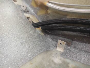
From the aft side to the nose in the pic below, I secured (not final) the hell hole ends of each oil line to their respective fitting (bottom hose to oil pump & top hose to firewall engine oil return fitting), while in the back seat area I secured the oil lines to the sidewall with an Adel clamp using a shared hardpoint with the thigh support sump fuel feed lines.
The front wall of the thigh support sump is actually a bulkhead that goes from one side wall to the other, and in this bulkhead –for the oil line passthroughs– are 2 vertically stacked hex cutouts matching the outline of the 1/2″-to-3/8″ reducer fittings. I did a final attach of the 1/2″ oil lines on the left (aft) and 3/8″ oil lines on the right (front) to these reducers, that were subsequently secured into the bulkhead with silicone.
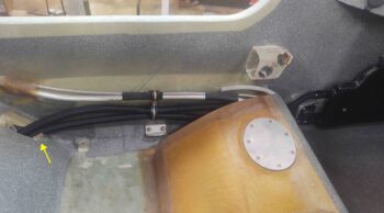
Finally, with all the oil lines in place, I slid the composite protective sleeve (yellow arrow) under the lower oil line at the back seat bulkhead opening.
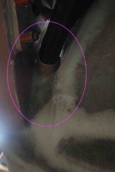
I also did a final mount of the 3/8″ lines to the heat exchanger. The zip tie is to position the reducers in the bulkhead cutouts, as I applied a decent amount of silicone RTV to secure the reducers in their respective hex openings.
A closer shot of the oil line composite protective sleeve. I floxed and glassed the protective sleeve both on the front and back of the seat. Here’s the front side…
And here’s the aft/under side of the rear seat.
Since the composite oil line protective sleeve sat just a hair proud inboard of the inside edge of the armrest, I taped up the interior edge of the armrest and mounted it while the flox and glass of the protective sleeve cures.
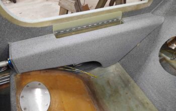
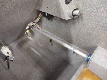
This pic also provides a good idea of what is visible and what isn’t with the armrest in place. Of course this view will change drastically once the seat core is in place as well.
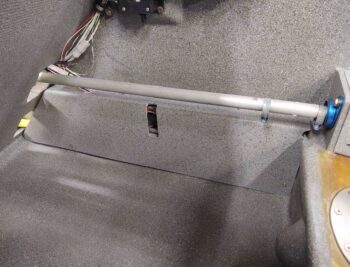
Regardless, here’s another shot of the back seat left armrest in place with the oil heat components installed.
My final task of the evening was to mount a click bond onto the face of my “map” pocket on the front seat right wall. This click bond is for yet another Adel clamp to secure the top wire bundle. Over the next 2-3 days I plan on adding top wire bundle hard points/securing features in this right front seat area.
Tomorrow I will attempt to finish the last remaining strake prerequisite tasks.