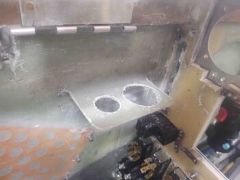
I started off today by pulling the peel ply on the repositioned/reglassed avionics bay electrical connector bracket. I then cleaned it up a bit and did a very quick razor trim. I still need to add another ply on the bottom, so I’ll do the final cleanup then.
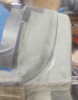
I then pulled the peel ply off the canopy left side aft lower “corner” where it interfaces with the Turtledeck. I assessed the shape and marked a cut line to remove the excess glass.
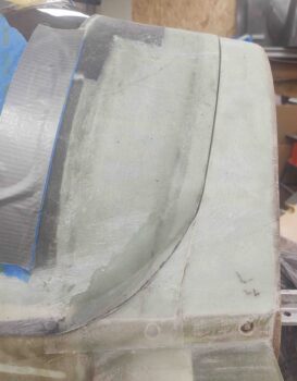
Here we have the new edge on the canopy left side aft lower “corner”…. I think it’s a vast improvement and looks much better. And yes, I should have done this the right way prior to painting the inside of the canopy . . . some things just get missed when you’re in a hurry.
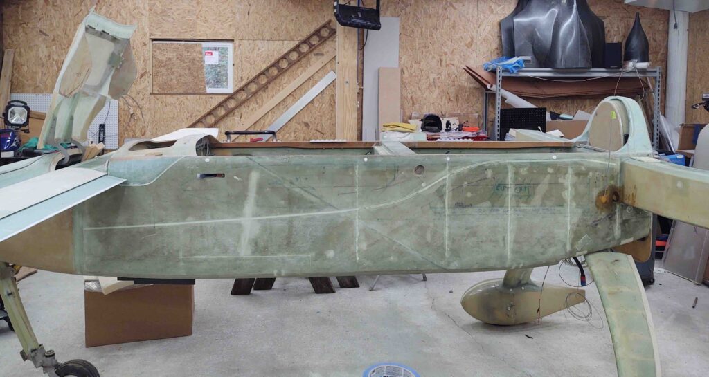
I then removed the canopy and roll bar in prep for the upcoming strake build. This is one reason I’ll need to wait a bit to dial in the canopy latch handle configuration. The other significant reason is I want/need (for efficiency) my milling machine and lathe to be online and CNC’d to spit out much higher tolerance parts much quicker than I can do by hand.
I’ll need the wings to be on before I start measuring and dialing in all the pieces parts for the strake. I don’t really have any help so it will be a one-man job. To make the job of mounting the wings and removing them much easier, I am going to knock out the reversed and secured wing bolt mod that so many canardians do.
If you haven’t heard of this it is simply having the wing bolts stick out of the CS spar and then having a U-channel bracket that secures them both to the interior CS spar aft wall, and moreover keeps them from spinning. This can be done however the owner/builder wants, with just the outboard bolts or the inboard bolts as well. I’ll be doing all of them in this manner. Then the wing mounting process can be a one-person affair by simply sliding the wing onto the bolts and then ratcheting the respective nuts onto each bolt.
My buddy Marco just did this mod to his flying Long-EZ and had some great tips for me (I’ll cover them as I do this wing bolt mounting mod). One of those of tips, that he researched and discussed with the Old Guard of the canard world, is cutting an access hole in the end of the CS Spar to more easily do the mod. I may not have needed to do this if my setup wasn’t disrupted by yet another mod that I did when building the CS spar: the wire/cable tube I installed that ends on the lower aft corner of the CS Spar’s outboard face.
Why the lower aft corner? If I go back and look at my build log it would probably say, but right now my only guess is that wire/cable tube exit location aligns with the wing wire/ cable channel. Regardless, I can’t merely measure, cut and slide a U-channel in place since I have to work around this wire/cable tube.
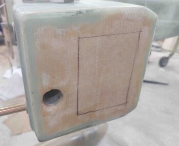
Moreover, whereas Marco used a large hole saw to create a temporary access hole to mount his wing bolts in the spar, I decided to make mine rectangular, with the sides angled somewhat like how you’d cut the top of a pumpkin if making a Jack-O-Lantern. So I marked my temporary access hatch outline.
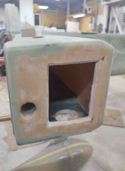
Then cut it out and vacuumed up the mess.
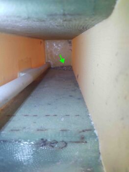
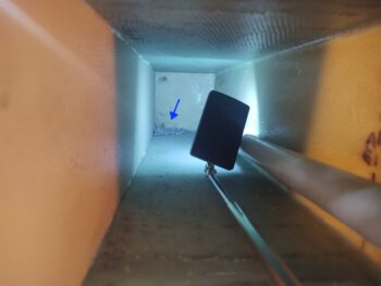
Looking around at my 8-year-old work —akin to opening up yet another time capsule on this bird— I noted a big ‘ol pile of metal shavings in the front inboard corner of the spar. Clearly from when I drilled the wing bolt holes. I of course vacuumed those out as well.
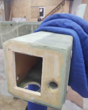
I then cut the same temporary access hole at the left end of the CS spar.
And just like the right side had another pile of metal shavings from when I cut the wing bolt holes. Yep, these got vacuumed out as well.
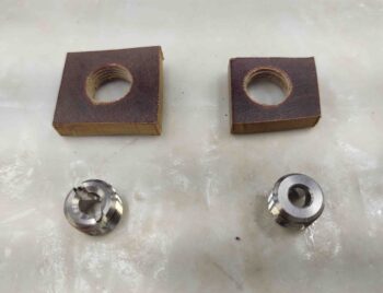
I then gathered up my phenolic plates with 1/2-20 tapped holes in them, along with the SkyBolt threaded ‘CAMLOC’ receptacles to assemble. I was going to flox the receptacles in tonight, but I wanted to wait until I had other glassing to do since I always make up too much epoxy, even with just a gram or two, than I need when doing such a small flox job.
I understand that these phenolic pieces look a bit wonky and not symmetrical. Part of my issue is these are 1/4″ thick, and my band saw is a small cheap one that wonders on any thick piece. The size difference is due to the right one originally being just a test piece, but then I don’t like wasting expensive material, so I used it for this. Once embedded into the nose sidewall, these will never see the light of day and their hideous disfigurements hidden except for the couple of pics of them in this blog.
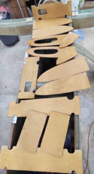
I then spent a couple of hours pulling peel ply and cleaning up the prefab Feather Light strake ribs and baffles that comes in their strake leading edge kit. I would say on about 25% of the surfaces they had overlapping peel ply which made it kind of a pain to remove… and took a bit longer. I would have saved 45 minutes if I didn’t have to deal with the multiple peel ply layered seams.
Still, I can’t complain that after less than 2 hours of peel ply removal I’m about 80-90% ready to start assembling/building my strakes.
I say 80-90% because some of the edges need to be cleaned up and better aligned with the original plans measurements and shapes… nothing overly extensive though.
Also, a significant mod that I plan to do is removing more of the aft sidewall in the back seat area, just forward of the CS spar, to add more arm access (read: comfort) into the baggage compartment for the GIB. I contacted Mike Beasley since he did this exact mod to query him on fuel capacity. You see, when you do this mod you angle the BAB baffle (fuel tank inboard wall) a lot more towards the back corner of the fuel tank. This takes away about 2.5 gallons of fuel each side.
Which leads us to mod #2. This is often done by builders regardless if they do the “GIB elbow room mod” above. And that is to simply use the slanted outboard OD rib –that is usually only for strake strength/rigidity– as the outboard fuel tank wall. This pushes fuel outboard and you gain a fair bit more fuel capacity. I know Nate Mullins did this, as a number of other builders did as well. IIRC, Wayne Blackler advised me to do this as well.
Now the downside. Since the spar angles aft from BL23 out to roughly BL55, putting fuel out here starts adding weight to your aft CG. Not ideal. Thus, as I often do, after my discussion with Mike I decided to compromise. Since this area is a “dead cell” or a simple open air pocket anyway, I will simply split it roughly in half and only use the more forward part of this open space. That will get me close to or slightly exceed reclaiming what would be my stock amount of fuel, while also giving me a much more comfortable back seat area, all with minimized (if any) negative affect on my aft CG.
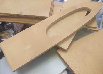
Here are the OD ribs, unfortunately with the lightening/access hole precut in them that I will fill in to configure another forward side fuel pocket. This will also require me to cut 3 mouse holes for normal tank fuel flow in the existing RB45 outboard fuel rib.
A note on the strake build. I’m comfortable at this point to start transitioning into the strake build although I’m not completely finished with the nose. With glass cure cycles I can start on the strakes and fill in the cure cycle periods with working on the nose, and vice versa.

