
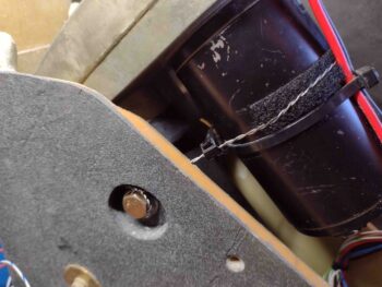
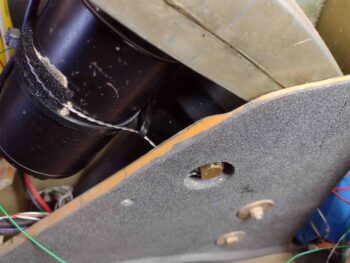
This morning I started out by finishing up a task I actually started a couple of days ago: safety wiring the pivot bolts on the Wilhemson nose gear actuator. Marc Zeitlin has pointed out that he has seen many times during canard pre-buy inspections that these bolts are dangerously loose and could allow the nose gear to collapse, etc. if one or both fall out.
To counter this issue, I swapped the bolts out to ones that have holes in the bolt head and then safety wired the bolts. Another factor here is that these bolts actually pivot back and forth just a hair as the nose gear goes in/up and out/down.
For this reason, and also not to cause harm to the actuator motor, I left the safety wire just a tad loose and then cinched up the slack with a zip tie. Near each bolt head I drilled holes into the NG30 at a steep angle going forward and angled in to avoid the 1/4″ aluminum mounting plates: another reason why I didn’t just wire these bolts together going straight across was not having the stainless steel wires tight against (read: sawing) the edges of the 1/4″ mounting plates.
Finally note that I put a strip of velcro along the actuator motor housing to offer it a little padding against the safety wire. I may refine my methodology as time goes by, but this of course will be assessed every year during the condition inspection.
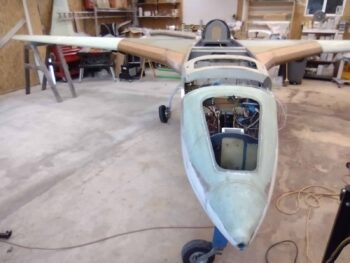
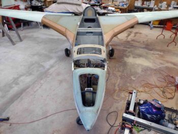
I then got busy cleaning, sweeping and organizing the shop in prep for mounting the wings onto the spar/strakes. I measured the wings and then took a bunch of measurements to figure out the best position for the fuselage in my shop to allow me at least a couple feet of space at the end of each wing to work on winglets once those go on. I then moved the fuselage into position at an angle in prep for re-mounting the wings.
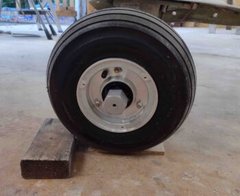
I then filled up the main gear tires to 80 psi before I leveled out the fuselage, spar and strakes by trying out a few different pieces of wood before finding the correct thickness under the left wheel. Getting everything leveled prior to the wings going on would then allow me to use Waiter’s (IFlyEZ.com) method in determining how the wings’ incidences compare to each other.
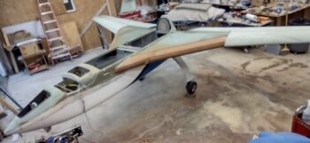
With my girlfriend Jessica’s help, I then mounted first the left wing, then a little while later the right.
Now, I actually took all these pics after I checked both wings angle of incidence compared to each other (see below) and think I still had the camera on “macro” when I took a bunch of the following pics… thus, forgive some of the haziness.
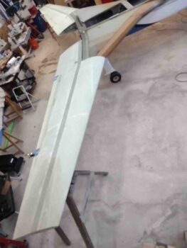
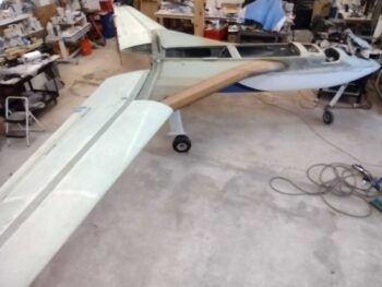
Here’s how the wing-to-strake intersections look currently on each side.
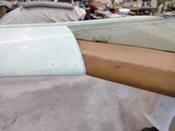
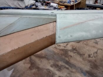
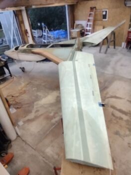
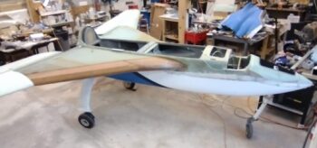
And just a bunch more shots of the wings mounted.
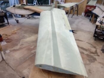
And a bunch with a bit more of the strakes showing . . .
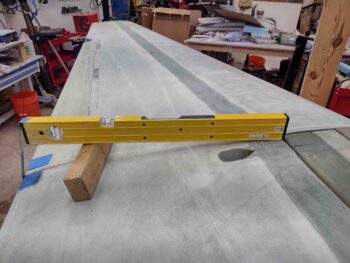
Again, following Waiter’s method (with minor changes due to level length) I set my level up on the BL 55.5 line with the level resting on the wing at the corner of the spar cap and the BL 55.5 front wing jut-out. I then get the bubble centered by using a block of wood . . .
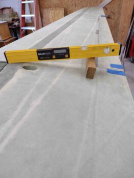
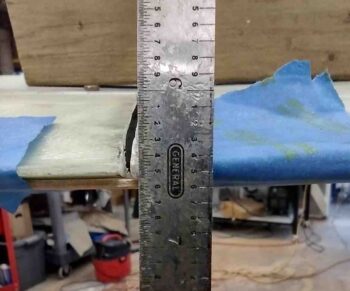
I then measure from the top aft corner of the level down to the top edge of the wing’s trailing edge. On the right wing this came out to be 6.5″ almost exactly on the nose.
Now, one measurement doesn’t tell you anything because we are comparing the respective wing incidences to each other. Clearly by ensuring the level has the bubble centered on each side, if one wing has a different incidence angle than the measurement from the aft top level corner to the trailing edge would be different than the other side.
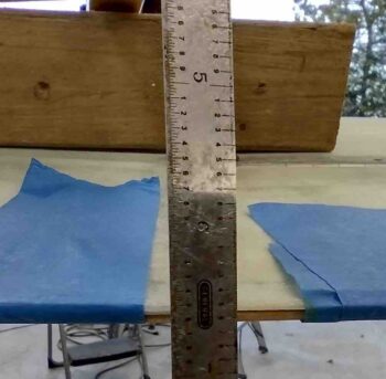
Here I have the level set up, bubble centered, on the left wing.
And the measurement I got was on the second big line in the middle between 6.4 and 6.5 inches, closer to 6.46″ I’d call it at the top edge of the wing’s trailing edge. But if we call it 6.45 then we’re still within 0.05″ of the right wing. Clearly this could be a difference in thickness of the spar cap, the TE, a very slight incident level, etc. But I’m going to call a delta of 0.05″ or less very good… and this will let me press forward with confidence in shaping each top strake to each wing knowing that the wings’ incidence angles are very close.
Although I don’t remember the numbers, I will note I did this same process when the wings were inverted and also got very good results.
With both of my wing’s angle of incidence being so close to each other, I called it a night and took Jessica to dinner…. today was definitely another milestone in the build worth celebrating!