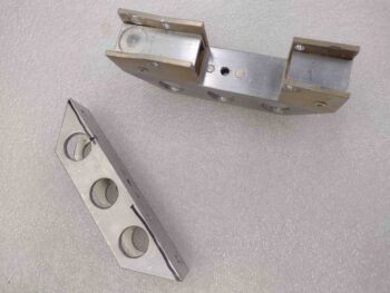
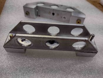
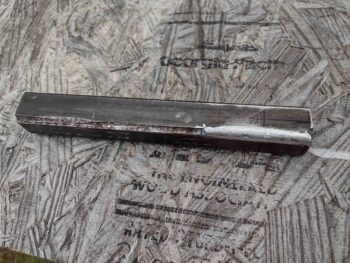
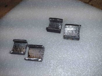
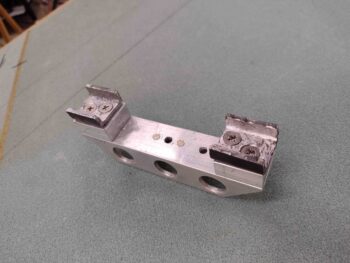
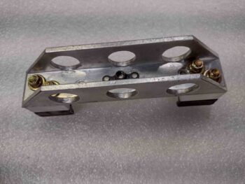
Today was all about upgrading the outboard wing bolt brackets with 4130 steel U-channels to ensure that the bolt heads will always be secured in place inside the channel. This did NOT happen with my last two (2) versions of the aluminum bolt brackets since —when push came to shove— the bolt head pushing on the U-channel bracket definitely shoved it aside as you can see in the top center of the pic below.
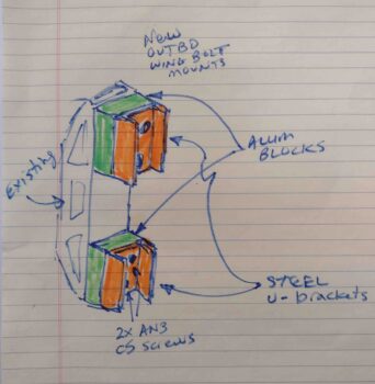
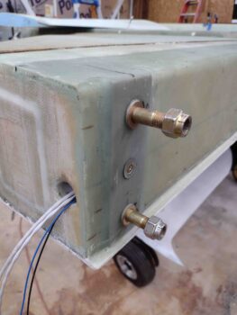
Here’s my proposed design that I came up with shortly after the second flipping of the bird, where once again I caught the shoulder —right where the threads end— of one of the four outboard wing bolts as I was tightening the nut, having failed to put that one extra washer on there. It turned out to be a good thing because it proved that wing bolt bracket version 2 was not up to the task of retaining the bolt head under more intense pressure. Clearly in my configuration I needed to use steel where the bracket contacts & secures the bolt head from spinning.
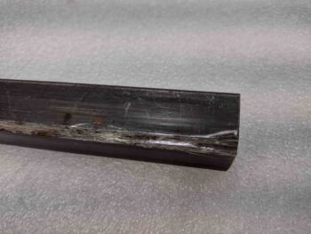
Here I got through dismantling the first bracket when I thought I would grab a pic of what I’m on about… note that I had mounted AN3 cross bolts to try to keep this exact issue from happening, without success.
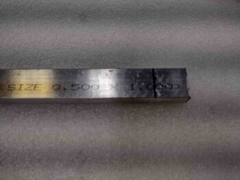
After referring to my proposed design for the MOD 3 brackets, I first rounded up some 1″ wide by 1/2″ thick 6061 aluminum stock.
Not looking for anything overly fancy, and wanting to get these things done ASAP, I simply used my large chop saw to cut 4 squares off the 6061 bar stock to be used as spacers.
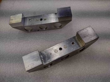
I then set the freshly cut 1″ x 1″ spacers into place on the bridge pieces where they will get mounted. I’ll remind you that I need a “bridge” since I have an internal cable conduit from the internal bulkhead outboard in each side of the spar that I need to work around… literally.
I then clamped the 1″ x 1″ x 1/2″ 6061 spacer blocks into place and drilled the screw holes closest to the top and bottom edges of the bridge brackets… these holes are getting reused while the second hole on each side will have to be re-drilled since the U-channels are significantly smaller at 1″ x 1″ than the ones on the version 2 bolt brackets. This is mainly for weight savings since the new U-channels will be 4130 steel.
Now, the 1″ x 1″ x 1/8″ 4130 steel square tubing stock I have on hand was one of the 2 original pieces I had ordered thinking I would use them for all the engine mount extrusions (yes, being quite the odd duck I used one 4130 extrusion on the top left corner). To make 90° angled extrusions I attempted to “rip” these square tubing pieces on my table saw with a cutoff wheel installed. The problem was that the cut off wheel would flex under pressure so I wasn’t getting a straight cut….
Thus I punted, only went with one 4130 steel engine mount extrusion and dumped this piece in the spare metal bin.
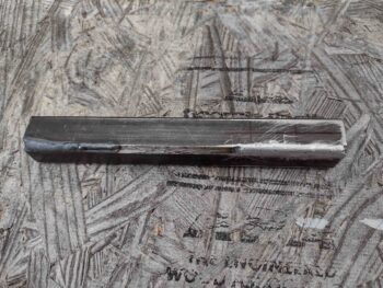
To ensure I have as much strength as possible on my U-channel brackets, I wanted to fill these ground down corners back in with steel before pressing forward… so out came the TIG welder.
I have to say, for not having TIG welded in well over a year I was pretty happy with the results. Here’s one side below.
And each opposite corner weld after I ground them down and cleaned them up.
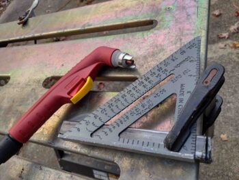
After some sanding and acetone I then set about to cut out the actual U-channels from my now freshly reinforced 4130 square tubing. I didn’t want to mess around with getting the plasma cutting table cleaned up, water added, software updated, etc, etc. so I simply hooked up the hand cutter, made my marks and pulled the trigger (ahem… literally!).
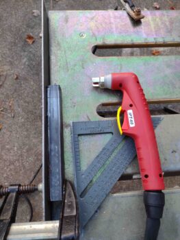
I started by cutting the end to clean it up… a “facing” plasma cut, if you will.
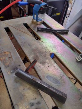
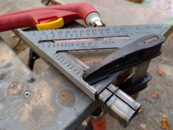
I then needed to rip both sides, 180° apart on opposite faces, to get the edge cuts for the U-channels. My estimation for the plasma kerf and standoff to center was off a hair, so one set of U-channel brackets came out about 1/8″ deeper than the others. No big deal really since they are the same relative to each other in their respective pairs.
You can see the difference in U-channel depths from my miscalculated “ripping” above in this pic below. Here I’m doing the cross cuts to actually cut off the first set of brackets.
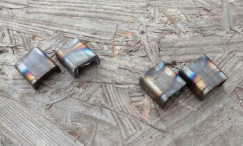
After 7 more cuts I had 2 pairs of 1″ x 1″ 4130 steel U-channel brackets, again with one set (right side) about an 1/8″ deeper than the other pair.
The plasma cutting process left some slag on the inside surfaces of the brackets. This combined with the original inside dimensions of the 4130 square tubing being just a bit less than the width of a 1/2″ wing bolt head, I needed to do some cleaning up and trimming internally on these freshly plasma-cut wing bolt brackets.
The insides aren’t pretty by any measure, but they will certainly work to test this MOD 3 design proof of concept and secure the wing bolts until I get around to making some final nice ones on the milling machine, etc.
I then spent a good little bit of time aligning, clamping and drilling out the screw holes and internal countersinks for the countersunk screws I used —note in the opposite direction of version 2 brackets. Again, I reused both the very top and bottom holes near each end, but had to drill completely new second inboard holes through the “bridge,” aluminum spacers and steel U-channel brackets.
Here’s the first MOD 3 bracket completed….
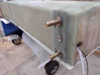
which I installed into the left side spar.
And here’s the second MOD 3 wing bolt bracket finished.
Which I then installed into the right side CS spar. With this one the center securing screw is just at the edge of the nutplate inside, so next time I install this bracket I’ll grab a next size larger screw to use.
I’m calling these new brackets a success. I will say that I was planning on getting the shop organized, moving stuff around including angling the fuselage to mount the wings… but it was later in the evening, I was just plain beat from a long day and Jess was making dinner. So with today’s mission complete I called it a night.

