
After refining my sequential task list, I got to work in the shop about noon.
My first task was to cover up the center open area of the cockpit with plastic to protect the finished cabin area from dust and errant epoxy, micro, etc. I found these thick strips of cardboard used as space filler in a foam box from ACS, so I trimmed some to length with scissors and taped them across the longerons somewhat as joists.
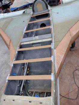
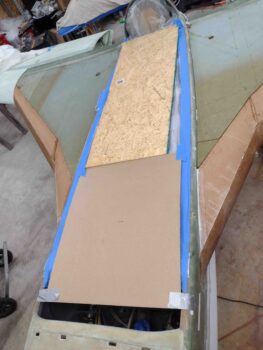
I then covered the cockpit from longeron to longeron with plastic. Then made myself some work surfaces with both a piece of plywood and thick cardboard.
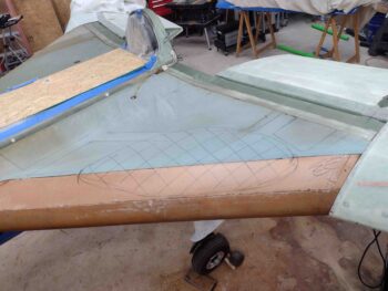
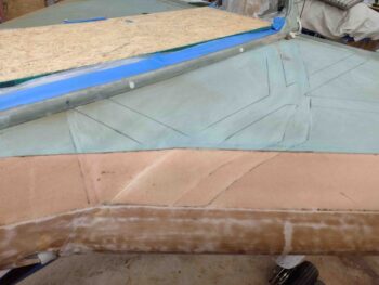
I then started sanding and shaping the left strake top and leading edge. The hashed area below was the area that gave me the most trouble. My R45 rib seems just a tad high on the top side thus the top (blue) and leading edge (tan) foam cores needed a bit more thinning in this area to get the strake surfaces smooth and even.
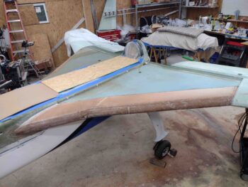
Here’s the left strake top and leading edge foam sanded, shaped and ready for glassing. I still need to prep the flox seam along the CS spar and sand the CS spar itself.
As per my usual weirdness, I had gone back and forth on wether or not I wanted the inboard left strake reinforcement plies to be on top where nearly all builders add them, or underneath the 2 large plies of UNI covering the strake. Well, since I wanted carbon fiber for the rigidity and stiffness, but like to protect bare CF with Kevlar for the puncture resistance and added strength, I decide to “bury” it by adding it first on the strake, then laying up the 2 plies of UNI over it.
I cut out the last remaining piece of UNI BID I had (thus the weird shape that was NOT the original planned shape…) and a covering piece of Kevlar as a second ply to “protect” the CF. With my known dimensions of the CF and Kevlar, I then laid them out on the strake top and marked their perimeters, then sanded a very slight depression for both plies into the top foam of the left strake.
Before I laid up the carbon fiber and Kevlar reinforcement plies, I needed to get even a little weirder. As anyone who has followed my build for more than a week knows, I like to kill the proverbial multiple birds with one stone. So a build task I needed to address was this one below: How do I secure the fuel site gage LED wires to the underside top/roof of the baggage compartment?
Well, I remember noting recently, paraphrasing another builder IIRC, to essentially always try to use gravity as your friend. And recalling my very efficient Dad who was always about “working smarter, not harder,” I decided to do both and simply drill a hole right near the fuel site gage up through the top strake and another one well forward of that and simply run the wire through a small channel in the foam (see below) laying atop the inside skin of the baggage compartment rather then wasting way more time in the painful and messy task of pinning these wires up to the top surfaces of the baggage compartment.
“NO FREE LUNCH” as my college economics professor used to love to retort… regarding the money supply system. But here I’m not going to open up a channel on the top of the strake without getting some extra benefit for my effort. Thus in my pondering this endeavor, I decided it would be a perfect time to add some strake baggage area lights and tie them into the single LED light on the fuel site gage… since these LEDs use so little current. Yes, this was obviously a little bit of an afterthought, but better now in my opinion while it was somewhat easier to do than later trying to reach into the bowels of the strake baggage compartments… especially if I was trying to tie into existing power wires.
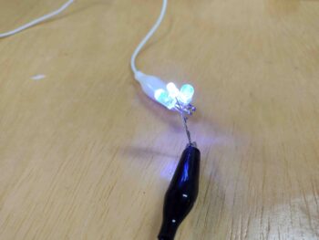
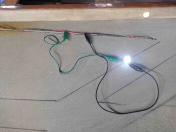
I had ordered a bunch of loose LEDs a long time ago and had them sitting around, so after 10 minutes of trial and error R&D I decided I liked one bright white LED combined with 2 blue LEDs. I wired them in parallel just in case any decided to die (unlikely) they would all be getting their own respective power feeds. Here’s the initial soldering of red and black wires to the LED leads.
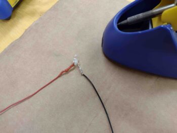
And a pic of the configuration: white LED in the middle with a blue LED on each side.
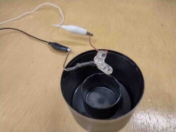
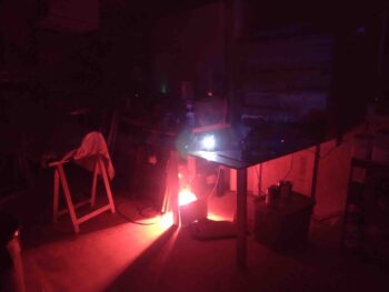
Here’s a test with all the lights off… except my impromptu heat lamp “heat box” for the E-Z Poxy hardeners. Not bad light output for 3 LEDs, and definitely plenty in my thinking for the baggage area.
Here’s the right strake baggage LED lights initial ops test. With the shop lights on, and from the side, you can see the blue-white-blue configuration.
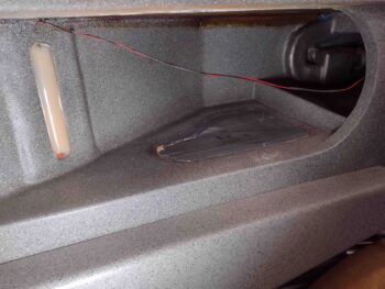
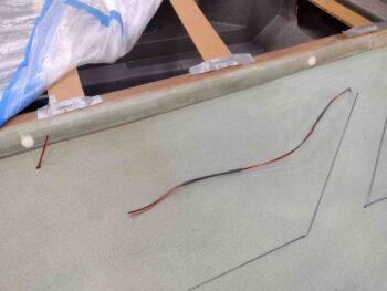
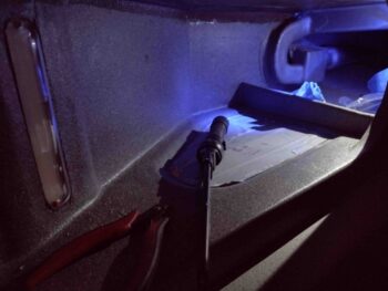
Here we have the initial holes drilled front and aft, with the cut fuel site gage LED wires run into each hole at each end. I cut the LED wires closer to the front side since this is where I’ll tie in the baggage compartment 3-LED bundled lights I made up above.
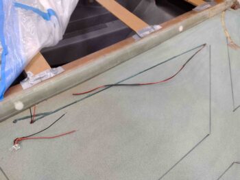
Which you can see I made a small branch off the main wire channel with a hole that the 3-LED bundle fits into deep inside the baggage compartment up against the original fuselage sidewall.
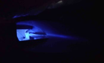
My test for the added baggage compartment blue/white LED light cluster was a smashing success IMO… here’s a shot of the front side strake opening into the baggage compartment (pilot’s seat).
And from the rear, with a bit more white light since the LED cluster is situated behind the oil heat RAM air duct/bridge…. which is exactly what I wanted. More actual light for the back seater to see into the baggage area.
However, after testing this a number of times I hit a snag. As you can see in this pic below, my fuel site gage LED light is inop. I was concerned about this since the wire leads on the site gage’s LED were so fragile and brittle they kept breaking off. When I soldered the wires to this left fuel site gage there was at most a 1/4″ of lLED lead wires showing, and honestly well shorter than that.
No matter what I tried, I wasn’t getting the LED inside the fuel site gage to power up, which is a real bummer because I was extremely pleased on how those turned out. Plus, having lit fuel site gages is important since I want to be able to see them on the EFIS camera I have pointing on each site gage.
To ensure I was getting power to the fuel site gage LED, and that my soldered splices were good, I stripped away a bit of the outer wire sheathing in 2 separate spots to expose some bare wire and tied in another LED to it. It fired up which tells me power to the fuel site gage LED is fine. It’s my connection to it right at its stubby leads that is the most likely culprit.
It was pretty darn late at this point… my happy success was now facing a good bit of PITA tasks to remedy this new curveball. I hadn’t really eaten all day and Jess was sweet enough to come over and cook me a late dinner while I struggled to figure out my fuel site gage LED woes. I called it a night and will pick up with this endeavor tomorrow.