
I started off today by taping the edges of the nose gear strut cover to serve as the curing base for the strut fairing layup, in order to have the 1-ply BID cure in place to match the profile of the gear strut.
I taped up a 2x piece of wood to serve as the glassing base while I worked on the 1-ply BID strut fairing layup.
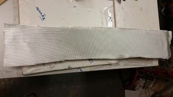
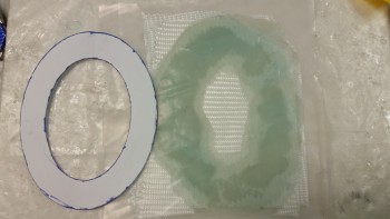
I mounted the 1/16″ G10 strut fairing onto the glassing board.
BTW, I’m adding a ply of BID to the front face of the strut fairing to provide strength to the fairing, texture for final surface finishing, and to add a little bit of depth to the cover since the head of a AN3 countersink screw is just over 0.070″. At 0.063″ thick, the G10 strut fairing needs another 20 thou or so to keep the mounting hole from being too wide, or deformed.
I then sanded the surface of the G10 strut fairing to provide some grit for the epoxy to grip to.
I then cut my ply of BID and set it in place.
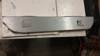
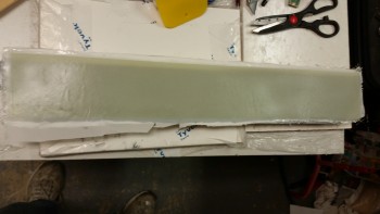
Below is a shot of the laid up & peel plied 1-ply of BID.
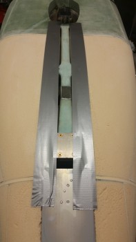
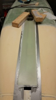
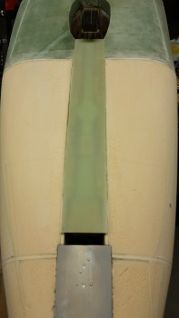
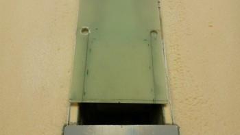
I then transferred the strut fairing over to the nose so that it would better conform to the profile of the nose strut after cure. I weighed down the aft side and simply duct-taped the forward bottom edge of the fairing to the NG5 plate.
 Since I had the glass cutting table opened up when I cut the BID for the strut fairing, I went ahead & cut a couple of pieces of BID for the gear doors. So immediately after I laid up the above strut fairing, I had just a bit of leftover epoxy (again, I’m cheap!) so I went ahead and glassed the gear doors. I don’t have any pics of the layup, but I have a shot below.
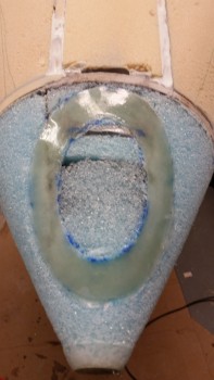
With the strut fairing & gear doors curing, I then started working on the landing light mounting flange ring. I grabbed the Dremel tool with a sanding drum on it and went to town on the existing flange. I removed a lot of glass & even broke through to the foam in a few spots, but when I finished the base was infinitely more level than it was before. I added a little flox to the leftover epoxy and applied it to the really ugly areas on the mounting flange ring.
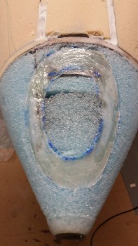
I then wet out my 3-ply prepregged BID setup.
And then laid up the 3-ply BID onto the landing light mounting flange. Below left is a shot with the top layer of prepreg plastic still in place, and the right pic shows the plastic removed. Again, the mounting flange ring was much smoother & level both before (albeit, since I contoured it) and after I laid up the new 3-ply BID.
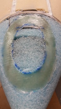
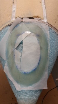
I then peel plied the 3-ply BID layup. Now, I may have to work this landing light mounting flange a little more to ensure that it is flat & level, but at this point it looked like the Dremel work had done the trick, making the flange nice & level.
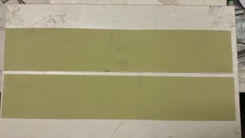
Fast forward a few hours later and here are the cured nose gear doors with a 1-ply BID layup on each.
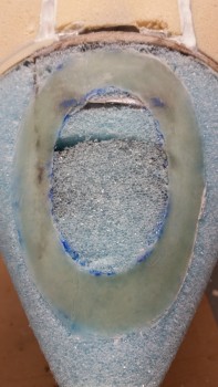
And here’s the cured landing light mounting flange ring. I’m very pleased with how smooth & even it came out this time around.
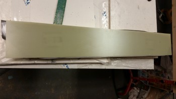
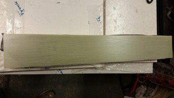
I also pulled the peel ply, razor trimmed and edge sanded the nose wheel strut fairing.
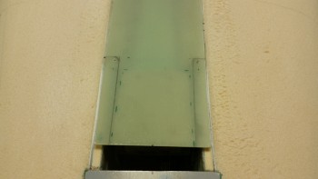
I then spent a while measuring & figuring out the cut marks for the forward end of the strut fairing. Since the top of the strut fairing will be hard mounted to the NG5 plate, then it follows that it will have to be shaped very close to the shape of NG5.
After I finalized the cut marks, I used a .310″ bit to drill the corners to create an inside radiused corner.
I know I sound like a broken record, but since it was late at night and I was out of things I could do on the strut fairing without the use of noisy power tools, I turned my sights on what I’m calling the nose “Exoskeleton.” I grabbed my last large piece of 1/4″ PVC foam and started figuring out the size & shape I needed to add to the nose to fair it into the existing nose, at least as best as I could ascertain.
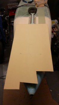
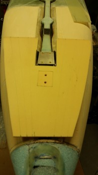
Although I forgot to get a pic of it all by itself, I had already mounted the rectangular H250 foam piece that will serve as the base for the nose bumper… after I determined the position of it in the surrounding 1/4″ PVC “Exoskeleton” foam, and creating a notch for it to fit.

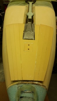
I then marked hash lines on the Exoskeleton foam (left) and then sliced down the lines that allowed the created gaps in the foam to expand to make the Exoskeleton flexible and able to wrap around a conical-shaped nose.
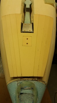
I then micro’d the nose Exoskeleton in place.
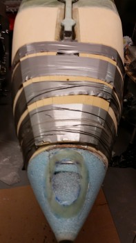
And wrapped it tightly with a BUNCH of duct tape.
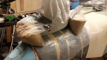
To ensure that the center section over the skid plate, the larger top corners & the center forward section were all firmly seated, I added some sandbags to weigh down these areas.
Tomorrow I’ll start by finishing the mounting of the nose gear strut fairing. After the strut fairing is in place, I can then dial in the shaping of the nose Exoskeleton to fair and merge it into a seamless part of the nose.