
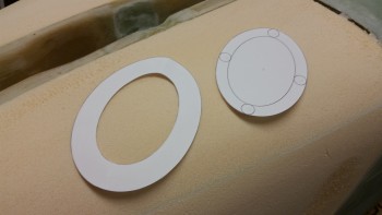
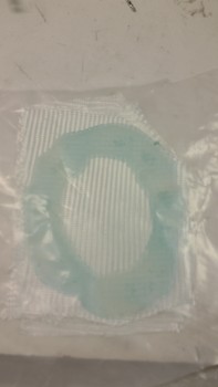
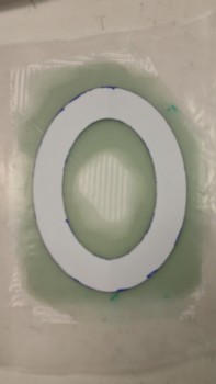
I started off today by figuring out the exact dimensions for the 5-ply BID landing light lens mounting flange ring (left in below pic) and the lens itself (below right). I made them up in Powerpoint, printed them & then cut them out. The mounting flange is 0.9″ wide and will be glassed into place so that the outer 0.4″ is under the skin of the nose, while the inner 0.5″ will have nutplates installed and will provide a mounting flange for the landing light lens cover.
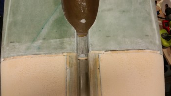
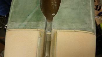
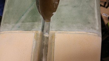
Down in the shop I wanted to get some epoxy curing as soon as possible since I have a lot of prerequisite steps before glassing the nose. My first task was to clean up the channel between the fuselage & the added nose foam that is technically the bottom of F22 that, again, was created when I left the 1.75″ foam its original width (vs the old original 1.6″ foam). I added a second pic to show a little bit more contrast & clarity.
I measured the depth of the channel at 0.2″ and then cut some H250 foam strips to fit.
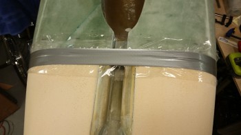
I then floxed in the H250 foam strips into the F22 channel.
I then taped the foam strips into place to get them set in place better.
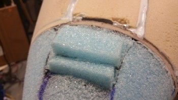
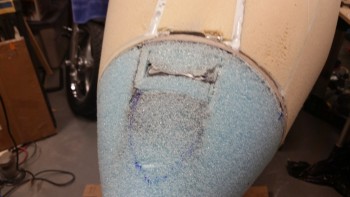
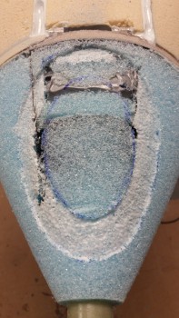
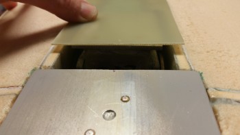
I then turned to working on the blue foam surround the landing light. With the nose so small, it’s a very tight fit of the landing light in the blue foam nose cap. I cut some blue foam strips and 5-min glued them in place.
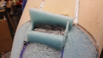
For the most part I was essentially improvising this foam install, and the only way I could figure out how to get the top piece to stay in was to simply 5-min glue it to the duct tape protecting the landing light. I’ll dig out the very thin layer of foam after the nose is skinned to create a slight gap between the light and the nose glass and/or the landing light lens.
After all the foam was in, I sanded it flush with the rest of the blue foam nose cap.
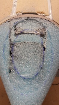
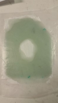
I then traced out the landing light lens mounting flange ring on the bottom of the foam nose cap.
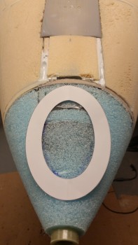
After marking up the mounting ring, I dug the foam out to create an approximately 0.1″ depression for the 5 plies of BID.
After rounding up 5 plies of BID, I whipped up some epoxy with fast hardener and wetted out the BID. I don’t normally prepreg more than 3 plies of glass at a time, but I made an exception here.
After ensuring the prepregged 5 plies of BID were completely wetted out, I traced out the landing light lens mounting flange template.
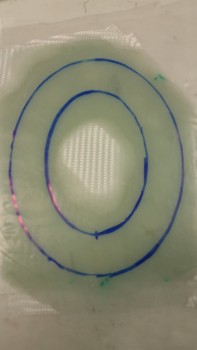
I then cut out the prepregged lens mount BID.
I then micro’d the foam depression on the nose.
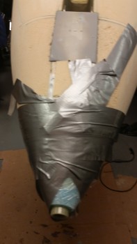
I laid up the prepregged 5 plies of BID, peel plied the glass, then wrapped it all in plastic wrap and duct tape to secure it down as tight as possible.
I went out to dinner and watched some playoff football while the floxed F22 gap foam inserts & the nose landing light BID cured. When I returned home, I peeled off the plastic wrap & duct tape to check how the floxed channel foam was looking.
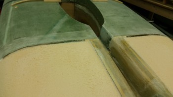
The filled channel looked really good. I then grabbed my hardboard sanding block with 36 grit sandpaper and worked on the cured flox for a bit. I’m really pleased with how the channel fill turned out.
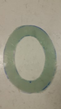
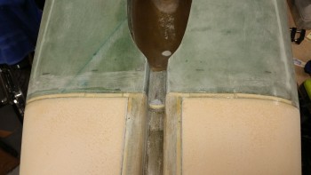
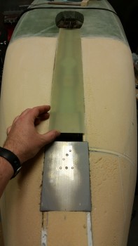
I checked the leftover micro & epoxy in the cups that I used to layup the landing light lens 5-ply BID mounting ring, and it was cured so I unwrapped the mounting flange ring layup. The layup looked good as for quality of the glass, but by binding it with the plastic & tape it pressed the glass into the very thin foam covered spots below, making for a fairly uneven surface, mainly towards the aft half.
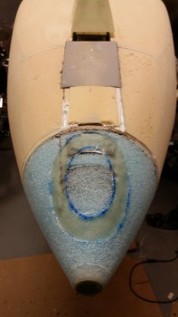
Although it will require more work, I am happy with the landing light lens mounting flange ring layup since it really strengthened the very weak foam around the landing light area. I half expected that it would need more work, even mentioning it in a conversation during dinner that the nose light foam & glass would most likely be “an iterative process.” (Sounds impressive huh?! ha!)
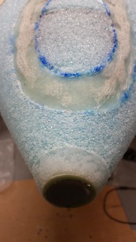
I then spent about 15 minutes sanding down the lens cover mounting flange ring. And once again, since it was late, I didn’t use any power tools. My plan tomorrow is to Dremel down the glass to get it smooth, and then back fill the good amount of glass that will inevitably be removed by the sanding with another 3 plies of BID.
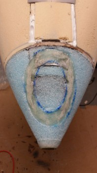
You might have noticed in the pic above that I floxed around the very front G10 ring to finish the cone-like shape of the nose. When I mixed up this flox I started by adding a good amount of Cab-o-Sil to the epoxy before adding the flox. After sanding the lens mount ring, I spent about 10 minutes rough sanding the green-staged flox.
Now for the bad news. I didn’t realize that my NG6B was mounted lower in the NG30s until I remounted the nose gear strut to cycle it up & down to check fit & clearance. When the nose gear strut settled into the strut cover it was clearly evident that the NG6B protruded out of the bottom of the nose significantly. I placed the strut fairing in place and measured the distance that the NG5 plate stuck out from the bottom of the NG30s and it came out exactly 0.15″.
As I pondered how exactly this could have occurred, I faintly recalled that to account for the fuselage bottom edge being 0.15″ lower than F22, that I would simply mount the NG8 brackets (the round aluminum brackets that hold the NG6B pivot bolt) and thus the NG6B pivot assembly 0.15″ lower. That all occurred in the Spring of 2013. Fast forward to the recent months where I apparently forgot that data point, resulting in my mounting the NG30s level with the bottom of the fuselage, not the bottom of the F22. Assessing this further, it probably wouldn’t have mattered either way since the lowering the NG6B is in relation to the bottom of the NG30s, so no matter in what manner I mounted the NG30s to F22, this would have still been an issue.
After working through possible fix actions, my initial thought is that I’ll lay in a slab of 1/4″ PVC foam around a good portion of the front nose area, which will also include the existing skid plate. I’ll flox in another 1/4″ 2024 aluminum H250 foam plate just big enough to serve as a base for the nose bumper, which will also be held in place by the multiple layers of nose glass in addition to the bolts clamping it between the bumper and the existing skid plate I just floxed into pace.
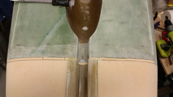
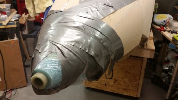
Below is a shot of the full nose gear strut fairing set in place.
Tomorrow I’ll be working fix actions for the added foam spacing to account for the NG6B overhang and also the landing light mounting flange ring cleanup & BID addition. To dial in the required width of foam that I need to add, I will most likely go ahead and mount the strut fairing as well. Of course, completing these tasks will push the glassing of the nose back at least another day.