
Finally!
I started off today by pulling the sandbags off the Nose “Exoskeleton” and checking the bond between the foam plies. It all looked good & only required a small amount of cleanup.
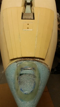
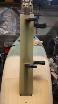
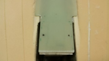
I then bundled up and took my strut cover outside & cut the top end so that it would fit inside the front NG30 compartment along with the NG5 plate. After bringing it back inside from the initial cut, it took a good 45 minutes of trial & error installing & removing to get the top strut cover to fit into the front of the channel as if it were mounted to the NG5 plate (which it will soon be). The issue is that my NG5 plate just barely clears the aft side of Napster (F1-3 bulkhead), with maybe 0.04″ clearance. So I kept having to not only trim the top of the strut fairing back, but also angle the top edge aft as well (both tasks via sanding with the hard sanding board). As you can see below, I finally dialed in the fit and then clamped the strut fairing into place, center & aligned on the gear strut.
I then drilled #10 holes from the backside of the gear strut through the G10 “nubbies” … remember those?
And mounted the die springs onto the AN3 bolts that I’m using temporarily until I get time to drill the countersinks for the screws. Let me tell you, those die springs are a true PITA to mount! I then tested the strut cover & it works like a champ. I plan on making a video during this next week so you you’ll be able to see it action.
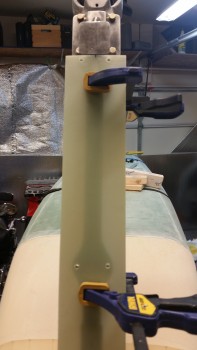
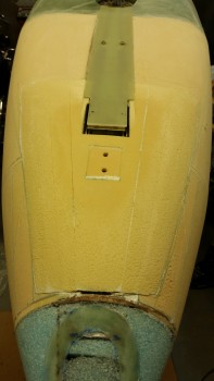
I then drilled a #8 hole on the each side of the upper strut fairing into the NG5 plate. I’ll tap these holes & use two #8 CS screws to mount the upper strut fairing to NG5. I’m also kicking around the idea of just using a couple of pop cherry rivets, so, we’ll see. I’m still weighing the pros & cons of each. BTW, I wanted to use #10 screws up top as well, to match the lower 2 sets of screws, but there just wasn’t enough meat on the overhanging NG5 plate to fit a #10 screw in there. Even a #8 is tight, but it will be plenty secure.
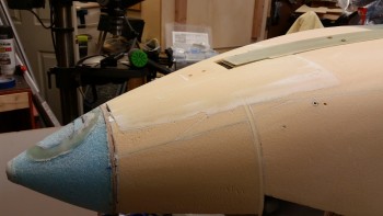
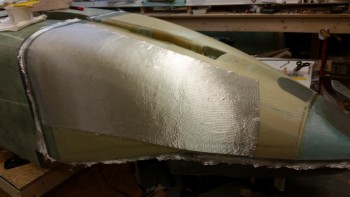
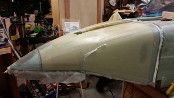
I then grabbed my Stanley SurForm cheese grater & started in on shaping the Exoskeleton with reckless abandon! (Ok, maybe not “reckless” . . . ) … ahem, with much vim & vigor! After 15 minutes I had it down to a fairly decent shape, as you can see in the 2 pics below.
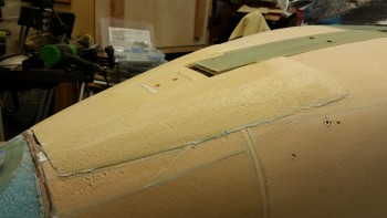
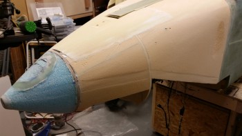
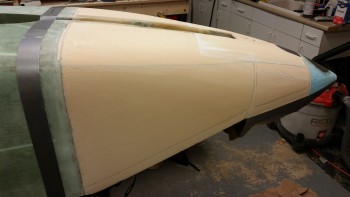
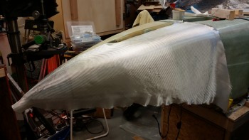
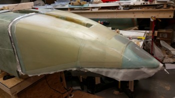
As per usual, I then used the long board with 36 grit sandpaper and really started getting the Exoskeleton to pretty much cease in being called any type of separate (albeit really cool! haha!) moniker. It was quickly becoming, simply, the nose again.
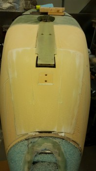
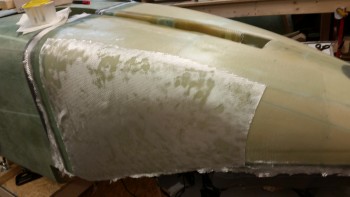
And here’s the finished product, ready for glass.
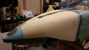
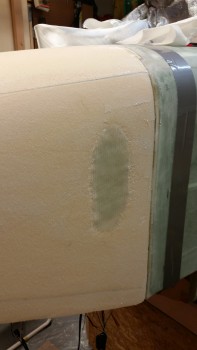
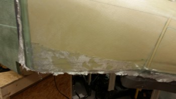
I measured out a 1.5″ joggle along the side of the nose where the top nose glass will secure the top foam & glass to the bottom I’m laying up here today. I was shooting for about 0.07″ deep, and no less than the 0.05″ deep, but the bottom line was to simply get some type of joggle in there to help mitigate the thickness of the top nose glass layup.
I then taped up the “bottom” edge (as it sits here) of the forward nose, the aft edge of where the fuselage overlap glass will be, and then embedded duct tape for future cutouts of both the Landing Light & the Taxi Light. I also removed the nose strut in preparation for glassing the nose.
I then taped up the interior nose gear actuator transit hole in the strut cover.
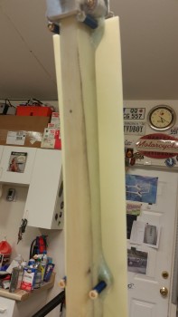
Here’s a shot of the joggle on the left side nose.
I then mixed up some micro using epoxy with slow hardener & micro’d the left side of the fuselage.
I then laid up BID ply #1 of 4 plies of BID that make up the main nose glass.
With the first ply laid up, I moved over to the Right side of the nose. My first order of business on the right side was to layup 2 small oval plies of BID in the oops area where I got a little too aggressive with the saw while initially cutting off the excess foam. In the pic below I got every gram of epoxy out of the cup to get this BID laid up initially (after I micro’d the right side). Once the cup was empty I mixed up a ton more epoxy & wetted out this BID patch more before applying BID ply #2.
Here is BID ply #2 before I wetted it out.
Here’s a shot of the nose after all 4 BID plies were laid up.
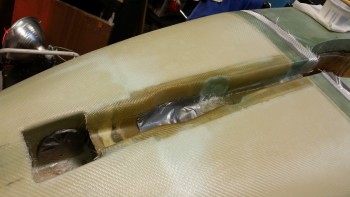
And here’s a closer view of the strut cover area. Except for the aft part of the inside strut cover — where I deepened it– I pretty much kept the overlap into the strut cover to about 1″, not including the top edge of the strut cover.
After I ensured all the initial 4 plies of BID were good, I started on the UNI reinforcement plies. Below I’m laying up the top UNI piece, which has its fiber orientation angled down following the top angle (remember, it’s upside down) of the aft nose sidewall.
Here’s the main UNI piece with its horizontal fiber orientation. Just like the final layup on the forward part of the fuselage, this UNI will extend the cantilever action of the fuselage onto the nose up to about midpoint of the battery compartment.
Finally, I laid up what I call my “Penance BID” for shaping the interior nose wall thinner than what is called out for in the Davenport nose plans. As I mentioned in a previous post, this BID ply is only as big as the aft big nose panel (the location of my crime!). Also, unlike the other 4 plies of BID whose fiber orientation was optional according the Long-EZ plans, I cut this BID ply at a 45° bias specifically to add strength.
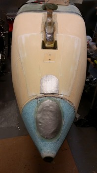
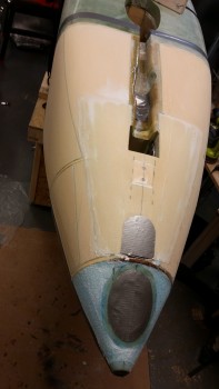
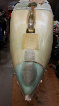
After I laid up my UNI reinforcement & Penance BID glass on the right side nose, I then glassed in my skid plate reinforcement glass. The first 2 plies were Kevlar, with the smallest piece going on first, then the 3 plies of BID with the larger piece going on before the smaller pieces of BID. Here’s the finished product below.
A side note: Since this is my first time laying up Kevlar, one thing that I wasn’t aware of, and something that I’ve come to seriously rely on when using MGS epoxy, is that Kevlar IS NOT transparent when wetted out like regular fiberglass! So when I laid up the first small piece of Kevlar, I immediately lost sight of my bolt holes for the nose bumper. I had to peel back the laid up ply of Kevlar and take a measurement to get a reference point to know where to drill once the nose is cured.
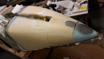
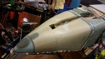
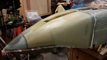
Below are simply left & right side shots of the completed nose glass layup.

I then spent at least an hour peel plying this damn thing! I started a list of all the small 1″ wide peel ply pieces that I was going to need for the front part of the nose before saying, “Screw it!” and getting one big piece for the front of the nose. Ahh, much better!
A left side shot of the peel plied nose.
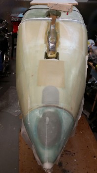
And a head-on shot of the completed & peel plied nose.
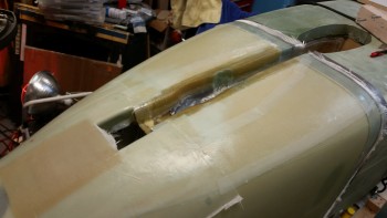
And for the final shot, a closer up view of the strut cover peel ply.
Tomorrow I plan to finish the strut fairing install & then start work on the gear doors, which I expect will take me a couple of days to get installed. I’ll also be working on the landing light and quite possibly the taxi light as well. I expect to be working on the nose for at least another week before everything is completed to where I want it to be.