
I started off today by pulling the peel ply, razor cutting & sanding down the cured wheel well glass layup from yesterday. It looks good & I’m very pleased with how the layup turned out.
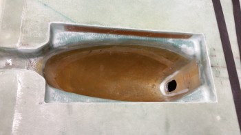
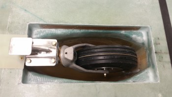
I then cycled the nose gear to make sure everything fit & clearances were good. Again, it all looked good.
I took a bit of time digging out the plastic Saran wrap from the embedded K1000-3 nutplates. I then tested the bolt holes with an AN3 bolt.
It took a bit of trial & error to trim the corners of the lower hinge half to get it installed, but when it was finished it fit great.
I also did the same on the left side hinge.
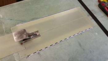
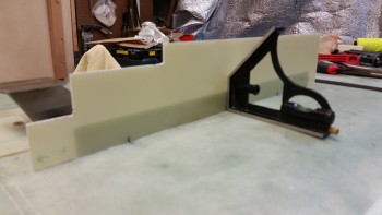
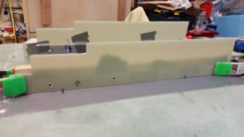
After trimming the gear doors to fit, I took a shot to see how it all looked together… cool stuff!
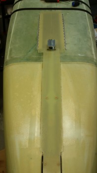
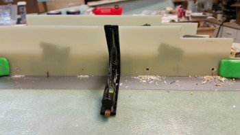
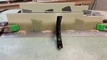
Here’s another shot of the strut fairing & gear doors together. I cut the gear doors a little funky so that they’d fit with the way I have the strut fairing configured. If I had put some more thought into my planning, I may have realized that if I had the bottom edge of the strut a half an inch higher than I wouldn’t have to wrap the gear doors around the bottom of the strut fairing. Also, you may note that the base for the T-shaped gear pedestal is exposed.
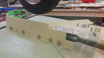
I’ll be honest, I definitely want gear doors since I think they enhance the look and are practical in keeping a good amount of cold air out of the wheel well, but they are a low priority for me so I wasn’t about to mess around with moving the microswitch on the nose gear actuator to increase the depth of the nose gear in the nose gear wheel well just to make the gear doors fit over this bracket. So, being “efficient” I just cut a notch in the doors around the damn thing! HA!
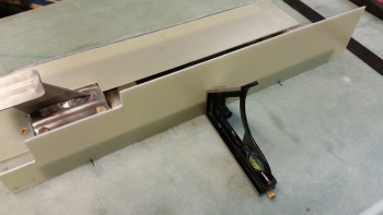
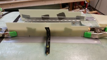
After a bit of sanding the edges to get the doors aligned I started prepping them to drill the holes for the mounting screws. First, I checked to ensure I had enough clearance by checking the doors open at a right angle.
I was going to hot glue the gear doors to the hinges to test the fit and swing of the doors, but found that duct tape held them in place fine. I did have some final tweaking in the position, but no more than 0.04″ in any direction. After messing with it a bit, I got the door & hinge geometry all dialed in.
I also marked thick crosshairs on the outboard side of the hinges that were visible through the gear door. I then clamped both the gear door & the hinge to a wood crosspiece to ensure that my position was locked in while drilling the holes.
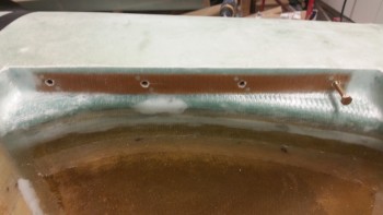
I started by drilling some small pilot holes (left) and then moved on to drilling 3/16″ holes through both the gear door & the top hinge plate (right).
Here are the 4 hinge bolt holes to mount the gear door to the hinge. I also had a mark made for the gear door spring mount, but I had to double check a couple things before drilling it.
I then drilled the bolt holes into the right side gear door & hinge.
Below you can see I mocked up the gear doors with click bonds. I actually messed around with installing the spring for a bit, but I haven’t nailed down my spring mounts yet and although pretty cool, it wasn’t working exactly correctly yet.
After the gear door hinge bolt holes were drilled, it was time to glass the exterior sides of the gear doors with click bonds installed.
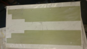
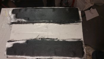
To make the gear doors stiffer, I planned on installing a ply of carbon fiber on each door.
I then cut a couple pieces of BID to be the final protective and added strength ply of the layup.
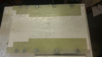
I then set the click bonds in place.
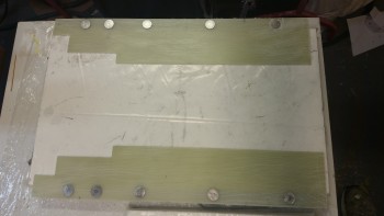
And then floxed them all in. To help mitigate any galvanic reaction between the click Bonds & the carbon fiber, I slathered the stainless steel click bonds with flox.
I then laid up the first ply of carbon fiber.
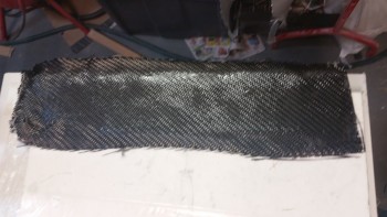
And then a ply of BID. I thought this shot below looks very cool.
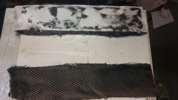
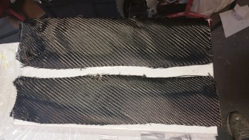
I then added epoxy to the carbon fiber on the gear door at the bottom of the pic & finished up the first door.
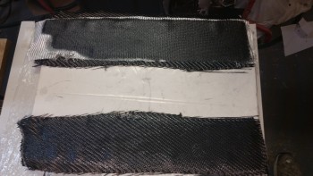
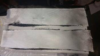
Here are both gear door layups complete, with 1 ply Carbon Fiber and 1 ply BID covering it.
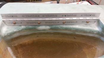
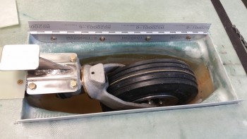
I also cut the spring that I installed and played around with for a few minutes. I cut the spring the width of the of wheel well bay, which is 6.4″. The spring I’m using is a stainless steel spring from McMaster-Carr (P/N: 9665K28).
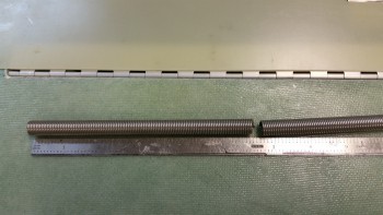
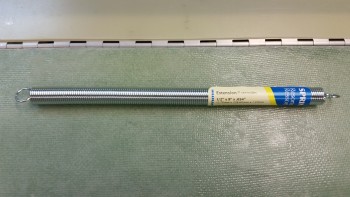
I bought the spring below a while back at Lowe’s to use but it’s not stainless steel, which is something that I definitely prefer.
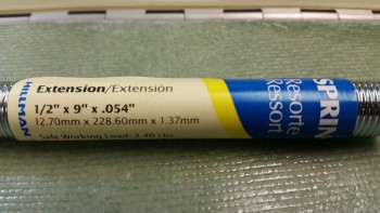
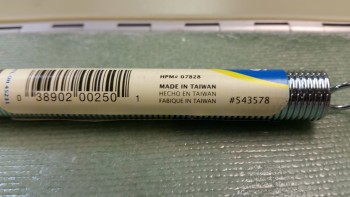
Here’s a close up of the dimensions & part number for this spring.
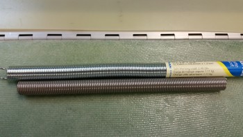
And a comparison of the diameter. The Lowe’s spring is a little bit bigger in diameter.
Tomorrow I plan to trim up the gear doors & get them mounted. I’ll then spend some time on finalizing the spring installation to get the gear doors working & check off Chapter 13 as complete. IF I have time, I may actually get to messing around with the landing light as well!