
After a couple of hours of some much needed project admin organization I started on the nose gear wheel well doors.
I re-measured out the dimensions of the wheel well & double checked that all the lines were square.
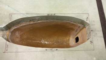
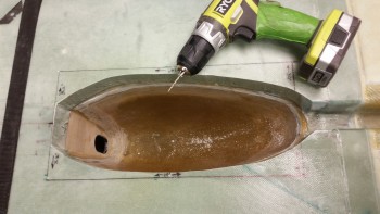
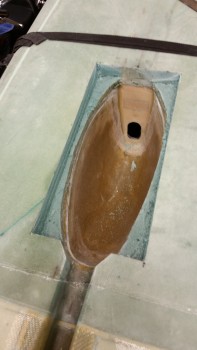
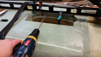
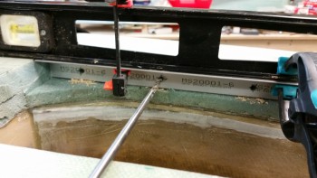
Since I would be cutting down an inch to remove the foam, I set a small drill bit in the drill at 1.1″ and made 3 test drills along each side to make sure I wasn’t going to slice a big hole into the floor of my fuselage when I cut out the sides of the wheel well. Thankfully, there were no breakthroughs when I drilled my test holes.
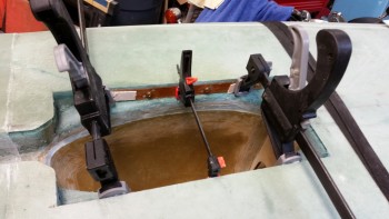
I then used my Fein saw to cut out the vertical and horizontal cuts.
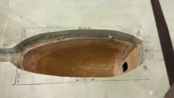
I then popped off each freshly cut side.
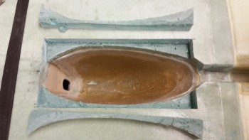
Here’s a shot of the freshly cut sides.
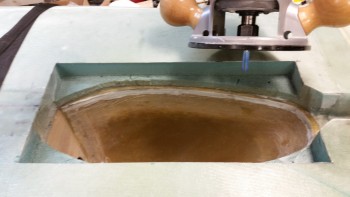
I then notched the sidewalls 1/16″ in from the side using a router to embed the phenolic hinge mounting nutplate backers.
I then cut the hinges at 13-15/16″ long, to allow for clearancee inside the 14″ long trough.
I then cut the phenolic hinge mounting nutplate backers & drilled the lower screw mounting holes into the hinges.
I then set the phenolic in place & temporarily mounted the hinges, one at a time, and drilled through the pre-drilled holes in the hinges to make the holes for the nutplates in the phenolic.
Here’s a closer shot of the hole-drilling in the phenolic.
Here are the phenolic hinge mounting nutplate backers after I riveted on the K1000-3 nutplates, 4 on each hinge mounting backer. After pondering on the upcoming 2-ply BID layup to hold each hinge mounting nutplate backer into place, I realized that I needed to trim about a 1/4″ off the top of each phenolic backer to allow me to create a flox corner edge above the phenolic backer and under the edge of the bottom fuselage glass skin to give the new glass layups something to bond to.
Otherwise I would have to radius the edges of the new wheel well sides and overlap the glass at least an inch onto the bottom of the fuselage. But clearly, with the hinges mounted to the sides, I didn’t want rounded edges since a nice 90° corner is what is desired for mounting these hinges.
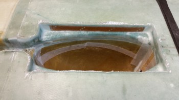
I then prepped the foam in the side walls to allow room for each nutplate in the foam when the hinge mounting backers get floxed into place.
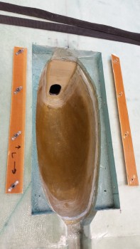
You can also see in the pic below the trimmed and sanded phenolic backers, an that I spent a good 30 minutes using the Dremel tool on the intersection between the nose wheel cover (NB) and the fuselage floor as well. After I finished smoothing out the added Ooops glass area & dead flox, I shaped the foam into a radius to allow the glass to flow smoothly from the new foam side walls overlapping down onto the NB sidewalls.
Finally, you can also see that I removed the foam from around the top underside “lip” of the bottom fuselage skin glass to create one continuous flox corner to give the BID layup an anchor to bond to & create a nice strong perimeter for this mod . . . no weakness allowed here!
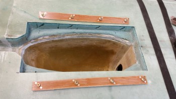
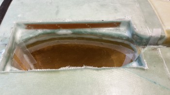
And here are the hinge nutplate backers floxed & clamped into place.
Since I was using fast hardener, things went pretty fast from the pic above. I had to work quickly to get all the flox into the flox corner that went around the entire upper edge (in relation to the pic). I then had to add both micro-slurry & thick micro paste to various areas, then cut the glass and start the layup. It was fairly frantic at times since there were so many intricate steps, but I ended up getting it all glassed as you can see below.
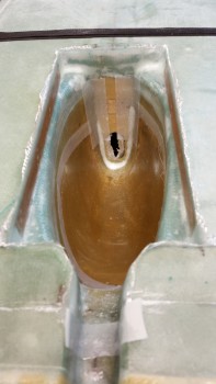
Here’s a shot of the final layup from the other side. You can also see that I peel plied the edges of the layups to help mitigate the gotchas. Trust me, if you’ve never had a fiberglass sliver sink into you, you’re not missing the experience. I went to flick some foam off the bottom of the nose and caught one that went DEEP… it hurt more than the usual snag & I needed yet another band-aid!
In addition to the wheel well sidewall layups, which includes the interior layup for securing the nose wheel cover (NB) to the fuselage, and in turn the Ooops glass heightening of the NB, the wheel well area is now all covered with 2-plies of BID, and the major glassing of the nose components making up the structural part of the nose is complete.
Out of curiosity I weighed the foam & glass pieces I removed from the sides of the wheel well at the beginning, and each was right about 0.65 oz. I then weighed one of the phenolic nutplate assembly and hinge, which came out to 3.55 oz. So subtract the 0.65 oz from the 3.55 oz gives 2.9 oz x 2 = 5.80 oz net total weight gain for just the phenolic nutplate assemblies & hinges. I’m estimating that with the BID, epoxy, FLOX, doors & spring that this mod will add about another 1.2 lbs in weight. I’d say more, but I would still be adding flox & BID to the wheel well even if I wasn’t going to add gear doors, but clearly just not as much of it.
Tomorrow I plan on finishing the gear doors and then working on the landing light lens cover for a bit.