
I guess I forgot about a critical piece when I started talking smack about getting the middle battery compartment floor foam piece micro’d in & glassed, and that being the last “real” foam piece of the nose that needed to be installed. The actual last official piece of foam that needed to get installed was the F4.1 mini-bulkhead, which I glassed on tonight.
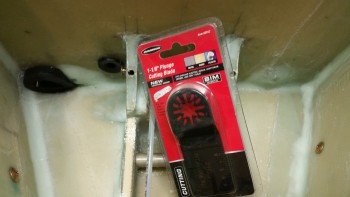
As for the nose gear backup battery foam insert piece, I found the blade I needed to rid the right side pocket corner of that nasty cured flox. It took around 4 rounds and a whole lot of vacuuming to get the flox ridges down to level. I’m always amazed at how tough flox is, and this was just some leftover stuff mixed into what was actually flocro.
 Here’s the new piece of BID laid up in the corner with the blue wing foam cross piece micro’d in place ready for some BID
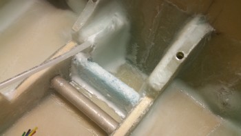
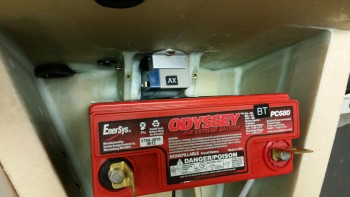
This time, to ensure the battery was going to fit [which I should have done on round #1], I taped up the battery and installed it. You’ll note that I took the leftover flox and added it around the left side of the battery mounting tube. I had planned on doing this for both sides, since I only need about 2″ of the middle of the tube clear for the strap, but I’ll have to assess the taxi light extension cable conduit placement before adding any flox to beef up the right side of the battery mounting tube.
As the nose gear back-up battery mounting “pocket” was curing, I drilled the hole for the mounting screw in the 1/16″ 6061 angled aluminum battery securing tab. I also cut & riveted up a K1000-3 nutplate assembly using 1/16″ phenolic as the base support material.
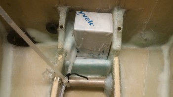
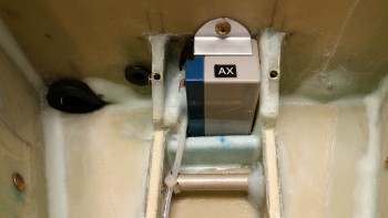
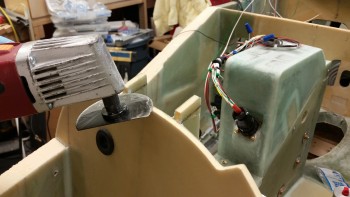
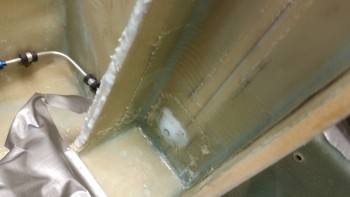
Here’s the nose gear backup battery mounting pocket all nice & cured with the 6061 aluminum mounting bracket in place. I cut a small piece of black rubber engine baffling for the battery to rest on before drilling the mounting hole into Napster. I can tell you the battery slides in with virtually zero wiggle room, so it’s secured very snuggly in this mounting pocket.
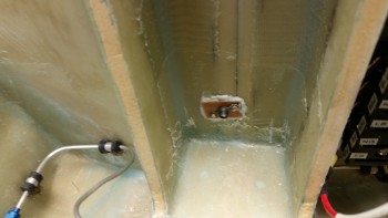
Below is a shot, albeit a warped angle view, of the fit & clearance between the nose gear backup battery and the main battery.
I’m sure you’ve noticed that every electrical component in this airplane has a 2-digit identification code. I maintain a spreadsheet and a diagram of all the electrical items with these ID codes. In fact, I’m so familiar with these codes now that I often use them as I make notes & write up my to-do lists. These component codes will always be the 2nd & 3rd digit in each of the two 6 digit codes that make up a label for a wire. The first digit in each code is 1 of 16 locations that have a specific letter identifier for a specific location in the airplane. For example, since the batteries sit in the nose –location ID code “N”– then if there were a wire between these batteries it would look something like this:
NBT000-NAX000
Again, with this coding schema I can look at a wire and tell where it’s coming from, what it’s going to, and what terminal, pin or port on the device at each end that it’s attached to.
I then started working on the F4.1 mini-bulkhead. This is the F6 bulkhead from the original plans. Before getting to this point, I did my research & assessment of the ELT mounting location. For a couple of months now I have had the idea of putting it in the nose. The ELT mounting location is one reason I’ve held off for so long on glassing in the F4.1 mini-bulkhead (along with needing access to the aft side of Napster to mount the nose gear backup battery mounting bracket nutplate assembly).
I had thought for a while now that I would mount the ELT above the parking brake on 2 foam/glass runners with the nose of the ELT sticking into a notch cut into the F4.1 mini-bulkhead. So earlier today, I spent about an hour and a half researching typically locations for ELTs in canards & other aircraft, and really poured over the installation manual for the ACK E-04 ELT. I concluded that I need to install the ELT just inside one of the baggage compartments, attached to & just on the other side of the fuselage wall adjacent to pilot’s seat back. One reason for this location is the 12″ ground plane leads that will have to be attached to the base of the antenna, which will go right behind the pilot’s seat. The other optional ELT location that I’m still considering is in the hellhole behind the GIB’s seat.
With the ELT out of the nose, the only remaining items that I had remaining to place were the clear bulkhead/wall-mounted brake reservoirs. Since the Matco-supplied nylon tubing is so stiff, I decided to mount the reservoirs as high and “far” away from the master cylinders as possible. I have 2 right-angled 90° fittings on order from ACS that will mount into the master cylinders that SHOULD allow the tubing flow from the respective reservoirs to attach to the master cylinders without too much contortion.
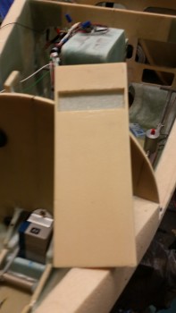
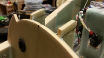
Ok, I said all this stuff above to simply note that the notch in the foam you see in the pic below is to embed a 0.267″ thick piece of phenolic into the 1/4″ piece of H250 foam. Note that I listed the phenolic thickness to highlight that it is slightly thicker than the foam, so there will be a raised edge that will have to be contended with.
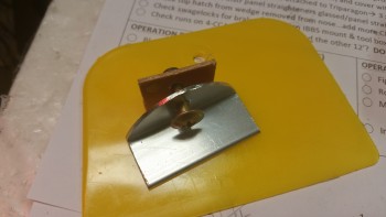
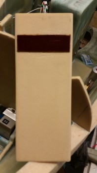
Here I’ve cut the phenolic & am testing its fit into the F4.1 foam.
I had waited until after I had cut & fit the phenolic into the foam to flocro in the gear backup battery mounting bracket nutplate assembly. On something like this nutplate assembly, which is hard to reach, I like to add just a bit of flox to my micro to ensure there’s a bit more strength so I don’t end up torquing on the screw while mounting the backup battery just to have the screw spin freely in a snapped off, buried, nutplate. I then used the same flocro-lite mix to embed the phenolic into the F4.1 foam face… after I had sanded each side of the phenolic to texture the surface for bonding.
At this point it was time to give Napster a much needed haircut. Since I created Napster from the F1-3 bulkhead by pre-cutting the area along the top of the Napster bulkhead to allow clearance for the nose hatch door [much bigger/longer than the original Davenport nose hatches… which there where two smaller hatches, one for each compartment] the original sized forward NG30 uprights clearly needed trimming. I had left them longer simply because I had never gotten around to trimming them, and you never know if internal nose configurations may have changed where they needed to remain longer. But the latter was not the case, so the uprights needed to be shortened to length.
First, I marked the cut lines.
Then grabbed the Fein tool — after putting the regular cutting blade back on.
And gave Napster a trim (after I removed the battery buss & relay, and taped up stuff in the immediate work area).
After cutting some fresh BID off the spool and setting it in plastic for a prepreg setup, I whipped up a new batch of epoxy with fast hardener. My first order of business was to add some more flocro (Yes, I’m on a flocro kick!) to the nose gear backup battery mounting bracket nutplate assembly (I love how long these descriptive titles can be… it’s like a German word or something! ha!). I then laid up a patch of BID over the nutplate assembly.
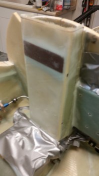
I then started to flocro up the uprights and grabbed this pic before I got too far into the weeds.
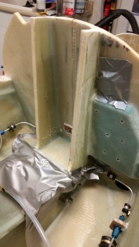
I wetted out the 2 plies of BID in the prepreg setup, cut it to size and then laid it up on the F4.1 mini-bulkhead that I had attached just minutes before to the uprights.
I have to tell you that what should have been a very standard layup just turned out, for lack of a better description, weird. To set the scene, this was much later in the evening since my older brother called as I was cutting the notch for the phenolic in the F4.1 bulkhead. Having not spoken to my brother in a very long time, I wanted to catch up. The long phone call pushed the layup back later into what turned into a VERY cold evening.
When I checked the shop temp, as I do fairly instinctively, it was in the high 60’s. Since the heater was set close to what it always was, it was definitely a clear indicator that the outside temp was very low. Normally, to keep utility bills down, and since I’m using MGS epoxy, I try to keep the shop between 70-73° F. So I kicked the heater on higher so that it was going while I mixed my epoxy.
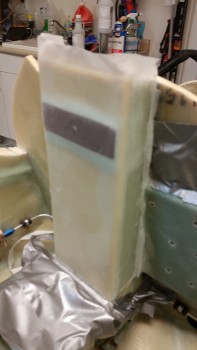
Ok, so as I’m laying up the prepregged glass onto the F4.1 face, it just does not seem to have any interest in bonding to the foam. I grabbed a brush and added more epoxy via stippling and I squeegeed the heck out of the face. Now, since the grain is so tight on H250 & H100 foam, I typically don’t add micro, and I didn’t here either.
I was working primarily on the left side of the nose when I went over to the right side to work on it from that side. It was then that I felt IT. There was a draft coming into the shop that felt like there was a 2′ diameter pipe of cold air blowing straight in from the Arctic! For the first time in a very long time, I grabbed my heat gun and heated up the layup. Then, as I was peel plying it, I hit it again with the heat gun. I then set up both a heat lamp and a normal shop light on layup and was able to maintain high 80’s to eventually nearly 100° F for surface temps on the curing glass.
But even then, I kept having to work the glass on the face of F4.1. Some layups just tend to be problematic, and this seems to be one of them.
I continue to check on the layup, but I won’t be surprised if I have some minor issues with this layup. Oh, well, this is definitely part of building an epoxy-based airplane.
With the F4.1 mini-bulkhead in place, I’ll be able to mount the brake reservoirs tomorrow. I’ll also be focused on getting the taxi light cable channel bracket constructed to fit onto the NG6B, which will then need some testing. Once that is complete, I can remount the gear strut, test the retract height of the gear into the strut channel & the nose wheel into the wheel well. When the retract height is dialed in, I’ll mount the the nose wheel well cover (NB) in prep for glassing in the pre-manufactured gear strut cover (SC). Finally, although I won’t get to it tomorrow most likely, I need to finish sanding & contouring the external surface of the nose. I’m still shooting to glass the nose either Friday or Saturday.