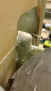
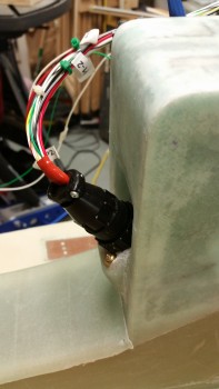
I started today by cleaning up the aft NG30 cover screw posts after my ugly 3-ply BID layups last night, including pulling off all the protective tape surrounding the layups.
I’ll work to clean up these screw posts later and add a ply of BID on the front (outboard) sides of them.
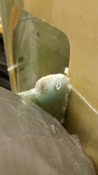
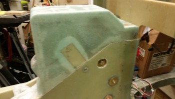
Here’s a shot of the left side of the mounted NG30 aft cover with both the middle & aft pair of screws installed. I’ll finalize installing the front pair of screws when I figure out exactly how the front NG30 cover & components will be installed (i.e. the parking brake).
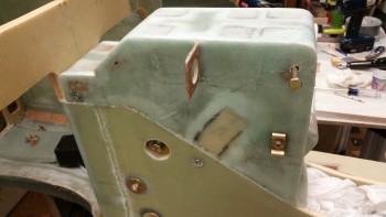
Here’s a shot of the right side of the aft NG30 cover. As you can see I started to drill out some of the holes for the Adel clamp nutplates.
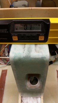
With the NG30 cover screwed in place nice & tight I checked the longitudinal axis again. Somewhere I lost 0.1° to make my cover off by 0.1° in comparison to the longerons. Oh well, close enough, I’ll take it.
I then ran to a mom & pop neighborhood hardware store that my buddy Greg told me about during his Christmas tie project. Again, although I should have my order in hand from ACS on Monday, I wanted to get the gear up/down warning microswitch in place if possible. Well, I ran over to the hardware store and hit the mother load. Not only did they have the microswitch screws that I needed, but a lot more hardware for mounting the electrical connectors, etc.
Here’s a shot of the installed gear up/down microswitch! Yeah!!!
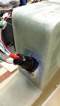
You may have noted that on one side the of AMP CPC connectors that I’m installing there’s a flange to mount the connector quasi-permanently to the whatever bracket, mount, etc. to which it will get mounted. I wanted to mount the P1 connector with the flange on the inside of the NG30 cover so that it could be removed by simply unscrewing the opposite half of the P1 connector, then removing the 4 screws to allow the connector to be removed. Otherwise I would have to literally remove the wire connectors from the backside of the connector housing.
However, to mount the connector in the way I wanted, I needed the connector mounting base with the phenolic insert to be thin enough to allow the outer side of the connector to screw on & lock into place. Since the angled mounting base was about 0.060″ too thick, it meant I had to get busy sanding it down on both the inside and outside. This took about 30 minutes all told, but I finally locked in the correct width.
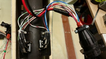
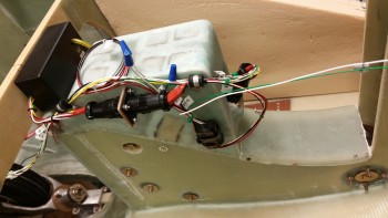
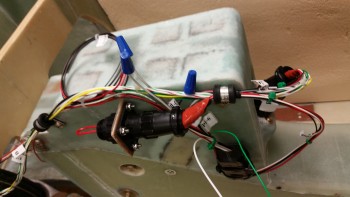
I then reinstalled the cover and mounted the P1 & P2 connectors into place. I also routed a bunch of the wires through a couple of mounted Adel clamps. I also mocked up the AEX to check its spacing. Admittedly, there’s still a lot of wires, but I’m really happy with the organization of all the wire runs. I’ll of course still continue to tweak these wiring configurations, but it’s a good starting point.
Since I’ll be sending the AEX back to Jack for repair in the next few days I made up a jumper plug for the AEX side of the P2 plug & installed it, as you can see in the pic below, so that I can run the actuator motor.
Here are a couple of shots of the installed P1 connector.
Although I do have some more minor tasks to finish on the NG30 cover, I’m calling it completed since all the major build tasks are done.
Tomorrow will be a light build day, but I do plan on getting some work done on the electrical connector pinout diagrams.

