Again!
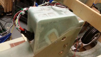
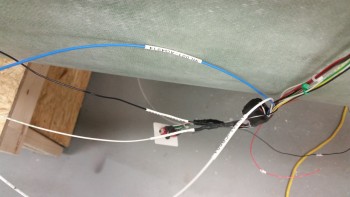
Here’s another shot of the installed & wired NG30 Aft Nose cover … not sure why I took this pic, or if it’s a holdover from yesterday, but here it is for your viewing pleasure!
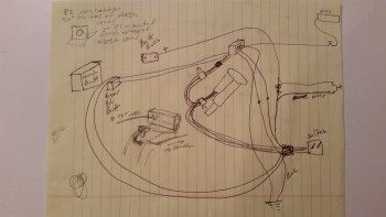
I also thought I would throw this up on the site before I threw it away. It’s my original chicken scratching diagram of the EZ Nose Lift nose gear wiring.
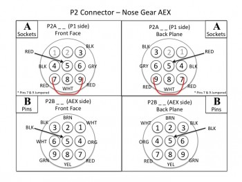
Finally, as for diagrams, I spent a few hours last night and a couple hours this morning making sure that I had my connector pins diagrammed out on paper. As of right now, I have about 7 AMP CPC connectors planned for use in my electrical system: the Infinity stick grips, throttle handle switches, etc. Each of those will have a pinout page depicting information on what wires are where & wire colors, and what connectors are being used, pins, sockets, notes and any pertinent info. Below is the first iteration of the P2 connector. Also, in addition to the P2 connector diagram, I finished the P1 diagram.
Later, while watching some football today, I took my list of wire label codes that I spent a couple hours last night researching & building to use to print out a bunch of wire labels. I’m fairly certain that I’ve already spelled out my code schema in detail here on this site, but after I work any wrinkles and kinks out of the system, I’ll touch base on my wiring code again.
In essence, I have two 6-digit codes separated by a dash that make up a wire label and then heat shrunk to the wire in an oriented sequence to depict where the wire is coming from & going to component-wise, and what location in the aircraft the wire is coming from and going to.
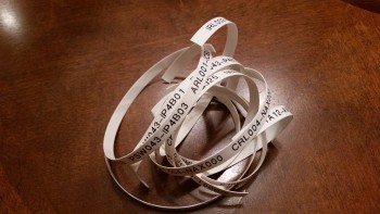
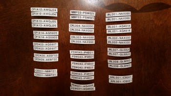
Here are the wire labels cut and ready to heat shrink onto the wires. I have them in pairs because my standard is to place a label about 6-8″ from each end of each wire. On longer wires there may be a third label thrown on approximately halfway the length of the wire.
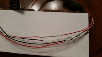
My first test case for the heat shrink wire labels was the landing brake wiring. I was very impressed with the legibility of the labels and the ease & speed of the whole process from printing the labels to heat shrinking them into place.
Since I have the nose gear wiring harness mocked up, I didn’t heat shrink some of the wires in place. I merely shrunk them down to a significant degree, maybe 80-90%… enough that they wouldn’t easily slide off, but that I could still slide them in their final locations (past the Adel clamps) later and then do a final heat shrink to keep them in place.
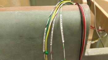
Below left is the pair of AEX power wires with incompletely shrunk wire labels, while in the right pic those labels were heat shrunk down to their final position.
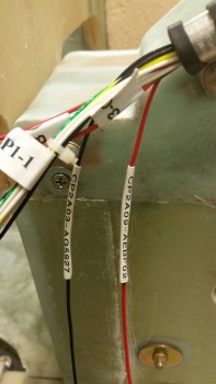
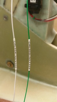
Here’s another couple of pics of my wire labeling endeavors this evening. The labels in the top pic are in their final location, whereas in the bottom pic those labels will be moved into their final position and given a final pass with the heat gun later.
I then moved on to a dirty little task: I cleaned up the ugly layups on the aft screw posts (or tabs), and then cut some of the foam away near the remaining good glass to create a trough for flox to go into to create stronger flox corner.
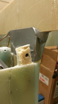
Here’s the left side aft screw post prepped for glass.
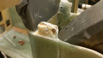
And here the right side aft screw post prepped for glass. Oh, and I guess I should have mentioned that I intentional set these posts very slightly inboard so that I could lay up a ply or two of glass on the front (outboard) side while still being able to seat the aft cover end around the posts. I did this by applying another 3-4 layers of tape –to emulate the thickness of BID–on the inside of the aft cover when I originally 5-min glued these screw posts into place.
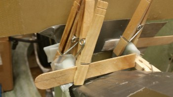
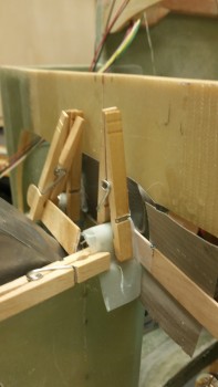
I only used 1 ply of BID after apply flox into the trenched edges, but the glass didn’t want to stay down so I forced it into place using clothespins.
Here’s a shot at another angle. I’m calling this ‘Ugly Layup Round 2.’
Tomorrow I’ll start on the remainder of the nose to get it completed.

