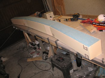
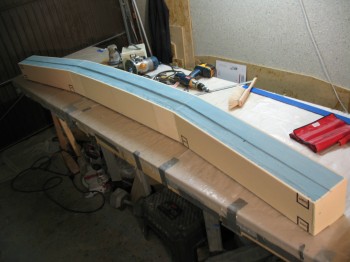
I started by routering out the bottom CS spar cap trough. I then hand sanded to final shape using the bottom templates to ensure the depth was correct (just like the top spar cap trough).
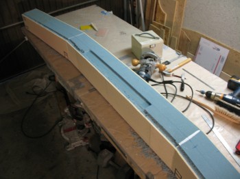
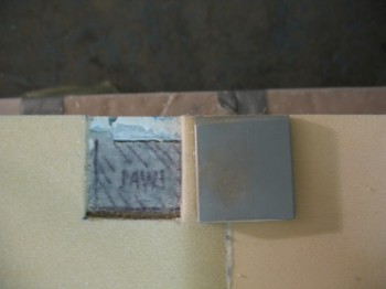
I used the Dremel tool to remove the 1/4″ yellow foam on the aft face of the CS spar over the interior (inside the spar box) mounted extrusions.
I cleaned up the newly exposed extrusion surfaces with Perma-Grit tools & sandpaper.
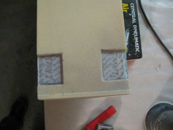
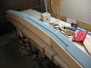
I floxed in 4 each LWA4s (2 each Outboard ends) & 2 each LWA5s (1 each side Inboard). I covered the extrusions with plastic & weighed down.
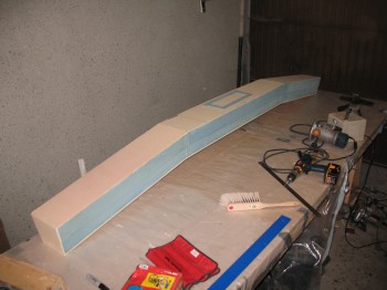
I then taped all the foam except that which would be covered by the shear web.
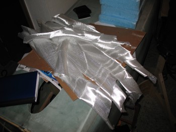
Finally, I cut the UNI as per plans (the original plans called for BID, but there was an optional mod to the layup schedule which allowed UNI to be used… saving a number of pounds by using the new UNI layup schedule).