
A significant mod that I’m making concerning the CS Spar is that I’m running the rudder cable conduits through the interior sidewalls of the fuselage & then through the front & back wall of the CS spar. Note, this is not an afterthought action, so I won’t just be merely drilling holes through the inside & outside glass surfaces of each spar face. What I will be doing, after much consultation with the old guard, is carefully separating the glass fibers so they stay intact and are simply rerouted about 0.04″ to 0.13″ to each side of the hole to make room for a small 3/16″ hole on the exterior spar walls, and a 1/4″ hole on the interior walls. Inside the spar I will run a phenolic conduit for the Nylaflow rudder cable conduit to run through. Thus, to cite an overused reference, there will be no glass harmed in the making of this CS spar.
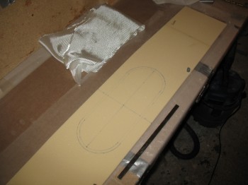
That being said, I forgot about the 0.5″ wedge that gets cut off the top front & bottom edge of the spar, so I set up the 2 holes for the rudder cable conduit 0.3″ from the edge, but I set them up incorrectly on the original “un-wedged” edge of the front spar face. No worries since this all gets removed when I sand down & remove the 0.5″ angle off the front corner edges. Of course I realized this after I had laid up the BID glass!
One other slight change I made was more out of curiosity than any build mod. I tacked a piece of peel ply under the BID on the very front spar piece where the 5″ x 14″ oval access hole will be cut out. The plans don’t have you peel ply this, but I went 5/16″ beyond the edge of the hole since after the hole foam/glass gets removed, 0.25″ of the foam gets removed & the glass on the edge of the hole prepped so the outer front face glass will have a good glass-to-glass bond when that layup is complete (i.e. inside spar glass bonded to outside spar glass).
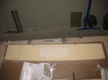
I prepped the foam for the spar’s front center face (interior side) with microslurry, then glassed the 1-ply BID layup. I then peel plied 1″ along the edges, since the edges will be micro’d to the blue foam edges at the front (currently top as jig is configured) of the spar box.
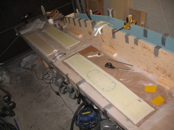
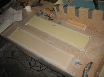
I then did the same thing with both the Left side & Right side spar front face pieces: microslurried then glassed a 1-ply BID layup with 1″ peel ply around the edges.
Again, these layups were all on the interior side of the pieces that will make up the front of the spar. The exterior front of the spar is pretty much the last thing that gets glassed on the spar (actually the 2 square end bulkheads are the last to get glassed, but who really counts those…?!)
After the front face pieces were glassed, I marked the foam inside the spar box with a Sharpie near the interior 2 bulkheads where the respective BID & UNI layups will be glassed.
I also marked the positions where the rudder cable conduit will exit on the aft CS spar wall (10.2″ L & R of CL & 1.8″ below the inside top wall of spar).