
I started off today reviewing the plans on installing the wings to the CS spar… to ensure I don’t miss anything.
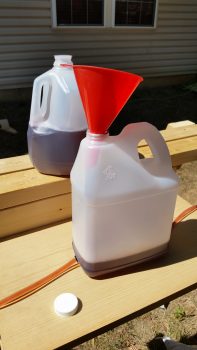
Then I constructed the water level system. I have 2 shots of that below, just to ensure some clarity.
The jug in the foreground is the actual reservoir for the water level system, while the milk jug in the back is simply the Kool-Aid colored fluid (plus a little dish soap) for the water level.
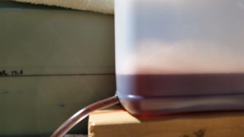
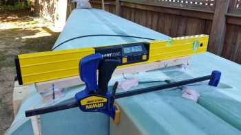
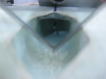
Here’s a closeup shot of the water level reservoir. It’s a bit out of focus, but you can see one of the two lines coming out of the bottom of the water level reservoir jug with a grommet installed to seal it all up. Also, note that the water level in the main reservoir is matched level with WL 17.4.
Here’s a quick video I shot detailing the general features of my water level system:
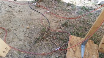
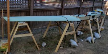
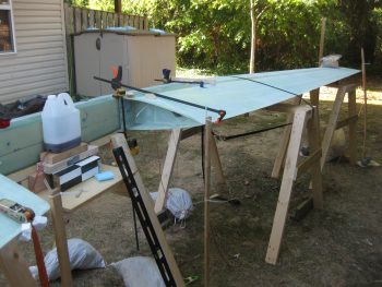
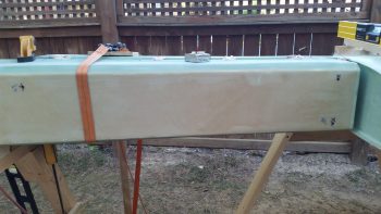
The water level is an amazing tool that allowed me to really dial in the rigging of the wings to the CS spar. Below is a shot of the Right Wing after I leveled it out and bondo’d it in place. Let me tell you, the term “herding cats” that all the other builders use to describe this part of the build is amazingly appropriate. It took about 2 hours per wing to really get all the variables synchronized to get the wings to level out appropriately. I remained about 0.15″ high on outboard leading and trailing edges, but I’ll take that!
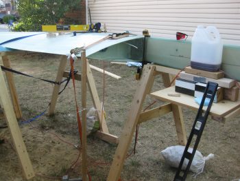
Here’s a wide angle shot showing the right wing rigged and work on the left wing to get it set.
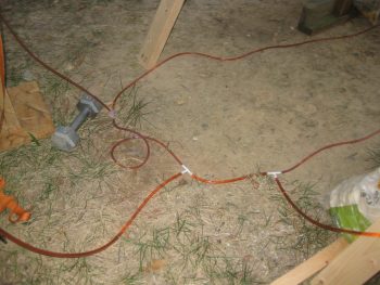
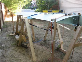
And here’s a couple shots of the left wing as I worked to get it level. The left wing took significantly longer than the right wing, and after getting all but the front inboard edge aligned, I finally (out of curiosity) set up the laser level to check the leading edges of both wings. For some reason my level board was way off on my left wing, so I committed a cardinal sin and went with the good level measurements on the other 3 corners, and used the laser level to fix the front corner (the BL 55.5 jut out) to match the right wing. One overriding reason I did this is the statement in the plans on pg 19-18: “Incidence must be set exact, or the airplane will roll.” Now, at that point the plans are talking about the setting of the level boards to 0°, but I also take that statement to mean the wings leveled in concert & in comparison to each other. Regardless, it certainly made everything work and align well on the left wing after I made the decision to use the laser level to match the leading edges vs going with the level board.
Here’s a shot of the right wing after it was secured in place by bondo. Both my wings are about 0.15″ high on the outboard end, but as I measured everything I concluded that my wings are definitely symmetrical!
After I bondo’d the left wing, I prepped for drilling the 1/8″ pilot holes through the front spare face and into the wing hard point extrusions.
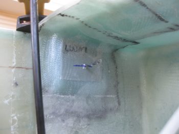
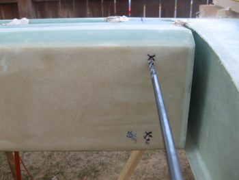
Below is a shot of the right wing’s inboard extrusion. Since I had to lift the inboard wing roots as high as they could feasibly go to align the wings, it lifted the embedded extrusions as well. Thus, the drilling is a little low to what I want on the inboard wing extrusions, but not too serious. I will also try to cheat the hole upwards as I drill out the bigger extrusion holes.
Here’s the same exact thing on the left side.
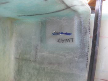
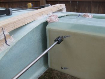
I will tell you one area that I’m ecstatic with, and that’s that I was able to get the 1/8″ pilot holes pretty much in the exact center of all the wing bolt troughs! *** whew!!!! *** I think this honestly must be the most anxiety that a canard builder can feel is when drilling these holes!
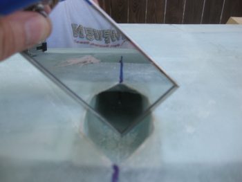
This shot is a bit blurry, but you can see the drill bit in it.
After all the 1/8″ pilot holes were drilled and verified, I then opened up the holes to 1/4″ as called out in the plans.
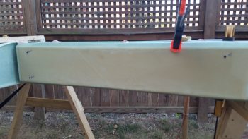
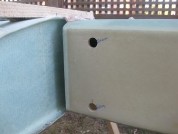
Below is both the right and left spar faces with 1/4″ pilot holes.
I then grabbed my 5/8″ spot face tool and opened up all the forward spar face holes with it.
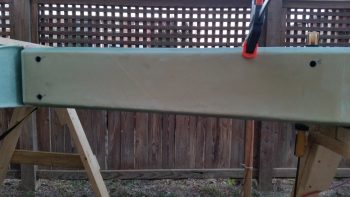
Here’s the right side holes opened up to 5/8″.
And another wider angle shot of the right side CS spar front face with the wing mounting holes opened up to 5/8″
After opening up the front spot face holes I then drilled the CS spar and main wing extrusion holes for a bit over 2 hours. I was having drill & drill battery problems, plus it was dark, so about 2100 I called it quits and packed up all my gear. I figure I got anywhere from a half to 3/4 of the way through on these holes.
I have another spot face bit, so tomorrow I plan on getting through the holes in no more than about 2 hours. From there I’ll trim and then flox in the LWA9 wing bolt hole inserts & let them cure in place overnight.