
Today was a heavy prep & work day, both in regards to mounting the wings to the CS spar and in finishing up my miscellaneous tasks from yesterday . . . so let’s get to it!
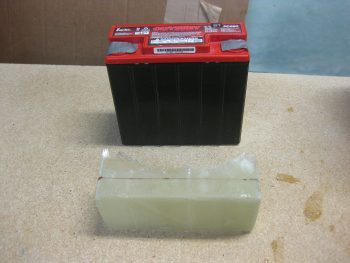
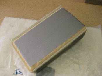
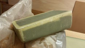
Of course the battery tray was nice & cured this morning…
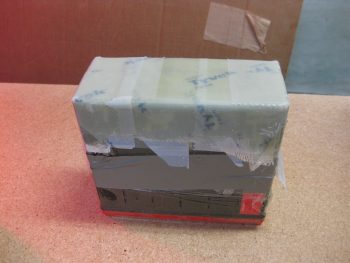
So I pulled off the peel ply, then the protective tape on the battery itself. I then worked the battery tray off the battery.
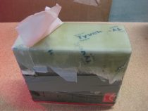
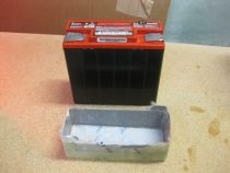
After I got the battery tray removed (and yes, it’s a tight fit!), I then pulled the tape from inside the battery tray.
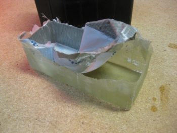
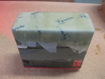
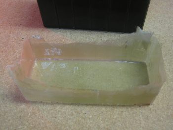
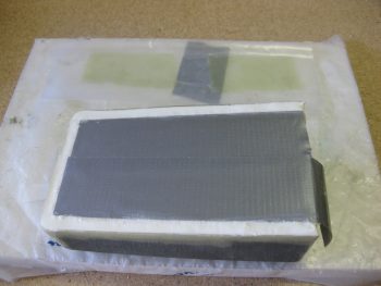
The result was nice in that there was no SNAFUs!
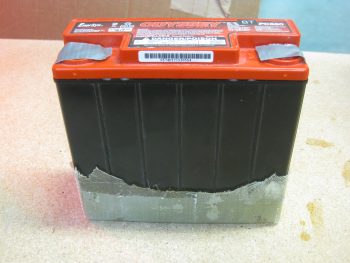
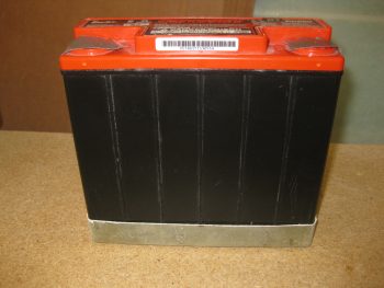
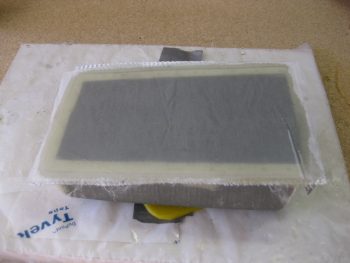
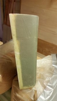
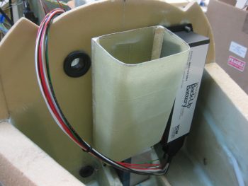
I then quickly set the battery back in the tray to test out the fit… nice & snug!
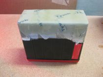
In my expert opinion (ha!) I’d say the tray looks a bit rough, so I marked it up for some trimming.
I also marked the tool box for trimming as well.
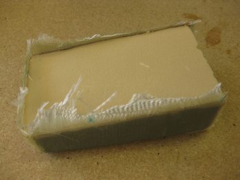
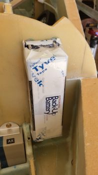
I then grabbed my Fein saw, the battery tray and the tool box and took them all outside for a trim. Here’s the result:
I’m really happy with the way the battery tray turned out.
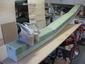
I then got to work to lay up the aft wall of the tool box with 3 plies of BID. Since I want a square corner on the back side of the tool box (where it hangs on the Napster bulkhead), I need flox corners (actually, I’ll be using Flocro… heavy on the micro). So I marked & cut those out.
I whipped up some epoxy and some Flocro, with about 70% micro to 30% flox and filled in the wedged Flocro corner troughs. Also, as you can see in the pic below just above the tool box (light green rectangles), I cut up 2 sets of 2-ply BID and pre-pregged them to lay up over the IBBS Clickbonds.
I laid up the 3 plies of BID on the aft wall of the tool box and then peel plied it.
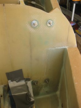
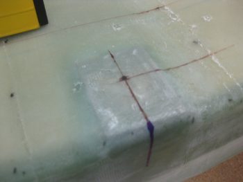
As for the IBBS Clickbonds, below are some shots of the IBBS being removed from the floxed-in Clickbonds.
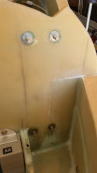
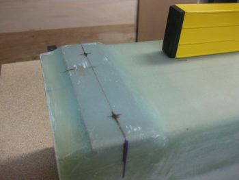
I then sanded all around the Clickbonds and cleaned them up to ready them for the 2-ply BID layup.
Here’s the BID layup that extends about 1″ from each Clickbond stud. I also peel plied the glass to give a good transition. To make it “form fitting” for the IBBS unit, I put the pre-preg plastic back in place.
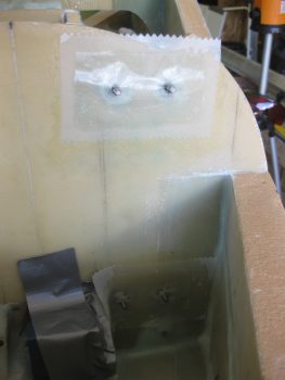
I then reset the IBBS unit and clamped it back in place like I had it last night. This will ensure that the BID immediately around the Clickbond posts lays down nice, flat & tight.
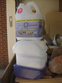
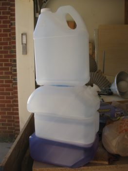
I took a break and ran up to Home Depot & to grab lunch. I wanted a better jug to use for the water level system (the old one is on the bottom in pics below) so I grabbed a plastic jug of Simple Green. I then poured the Simple Green into the old water container that I had considered using for the water level [it’s too big & heavy].
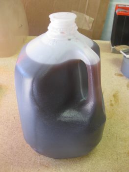
After getting the water level jug squared away, I then mixed up a few packets of Kool-Aid to use as coloring [Tip: Kool-Aid is WAY cheaper than food coloring!].
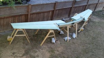
After getting a bunch of the preliminary prep work out of the way, it was time to finally break out the wings from their multi-year bondage in my work shop!
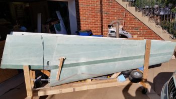
Although I actually took this pic a bit later, I wanted to post it here so you can get a good visual as to what I was doing.
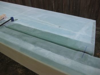
I started by clamping the ring wing to the CS spar to check the “A” & “B” lines as it states in the plans to do (“Waiter” really emphasizes this step as well). I have to say that the marks are very close between the wings & CS spar, but there is a bit of tweaking that I’ll do –on the order of 0.04″ to 0.07″– to better hit center mass of the extrusions while drilling.
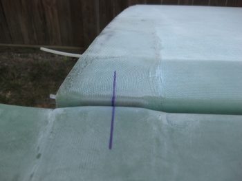
Here’s a shot of my right outboard alignment… not too bad.
And another shot to show the alignment.
Here’s a shot of the alignment on the left wing.
And the inboard bolt extrusion area on the left wing.
I wanted to take this pic not as much for showing the antenna wires from the wings, but the fact that by using that conduit that I installed between the outer & inner CS spar bulkheads, I was able to slide each antenna cable into the CS spar in about 5-10 seconds. Very EZ!
Back in the shop, and since I had my Fein saw ready, I chose to start to finalize another thing on my bucket list: the CS109 control stick tab. The problem with this tab simply has its roots in the fact that I bought the control system from the Cozy Girls. This isn’t to say anything bad about their components, because they’re awesome. The problem is that their stick mount straddles the round control stick tube while the old control stick setup sits on the inboard side of it, or shall I say 3/4″ inboard of the Cozy Girrrls stick setup.
My buddy & fellow EZ builder Dave Berenholtz points this out on his blog. I took heed after a discussion with him, and will be remounting a new one further inboard which will provide a bit more clearance for the Cozy Girrrls’ control stick between the stick and the immovable fuselage side wall. Since the back seat area was a bit cluttered, I’ll get to CS118 later. For now though I know it will be a 3 minute job to remove CS118.
I then set about drilling the 1/8″ pilot holes in the CS spar. The plans call for a #10 drill bit be used for the pilot holes, but then again I’m following a lot of Wayne Hicks’ advice and he recommends using a 1/8″ drill bit (it’s more forgivable & RE-adjustable if off center).
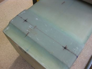
Since my spar narrows a bit more top-to-bottom than standard spars do to account for wing thickness, I had to be extra diligent on finalizing the positions of the plans dimensions for drilling wing bolt holes into the extrusions.
Here’s another markup on the inboard side of the strut.
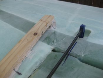
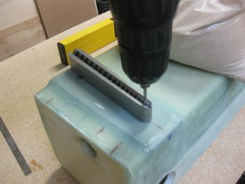
To ensure my holes are a good 90° to the face of the extrusion, I’ll be using my new drilling block.
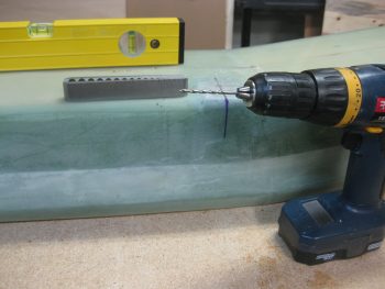
Below I’ve just drilled out the 2 outboard 1/8″ pilot holes in the spar on the right side.
And the same for the inboard extrusion.
I then flipped the CS Spar around and started in on the left side.
Here I am using the drilling jig to keep the bit straight.
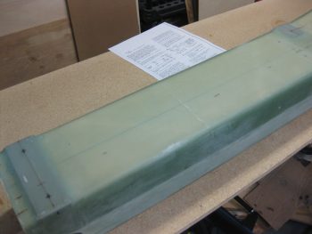
And Voila, here are the 1/8″ pilot holes drilled into the aft side of the spar.
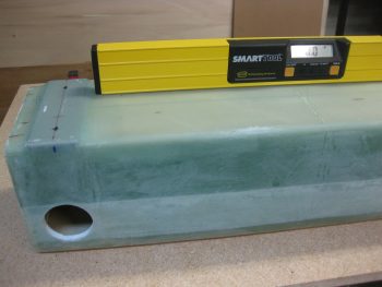
Then, as per plans, I marked up the front side of the CS spar for drilling the forward side spar boring holes. I have to state that when I started on the outboard holes it wasn’t until I got around to finding the inboard hole to drill that I realized the spar was upside down to me… which my outboard holes were way off! Not that it matters because these holes can be left open, and they’re close anyway that once I start using a 5/8″ bit they’ll go away… but it is somewhat of a testament of using a 1/8″ bit to start since it keeps the holes small & manageable.
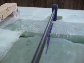
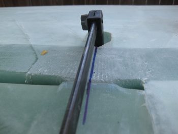
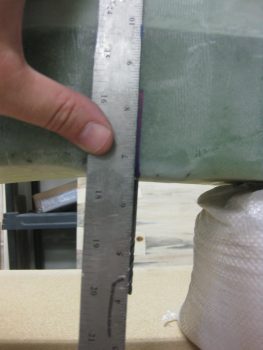
Here’s a shot of the long 1/8″ drill bit that I put into place after drilling each forward spar face hole.
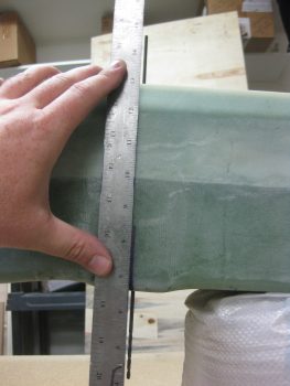
I used a long ruler to double check the angle of the drill bit on each hole so as to ensure that the bit wasn’t heading into the wing extrusions at an odd angle!
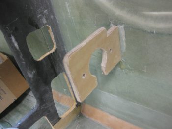
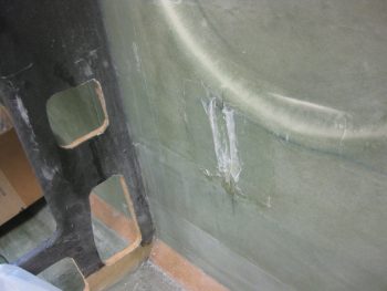
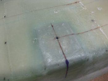
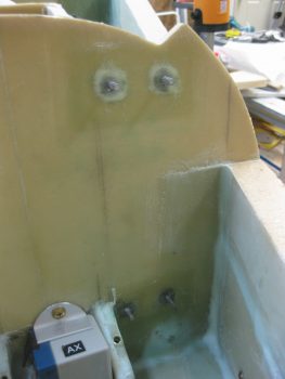
With Chapter 19 Step 1 of Step 11 complete, I then checked on the cure of the IBBS Clickbond glass. The epoxy was pretty much cured, so I very gently popped off the IBBS unit. Here’s the final shot of the IBBS Clickbonds glassed into place.
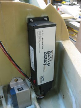
And here’s a trial mockup of the IBBS to ensure nothing is jacked up (which nothing was!) and to confirm clearance of the wiring harness & connector.
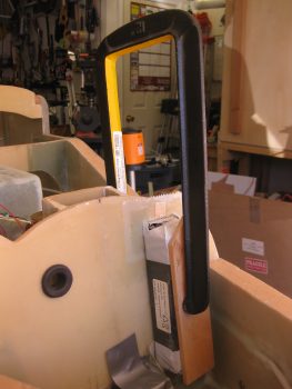
Finally, I got back to the nose Tool Box. I trimmed the edges with a Fein saw (earlier).
And then sanded them down.
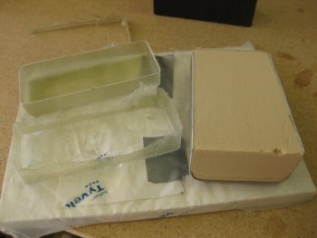
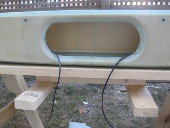
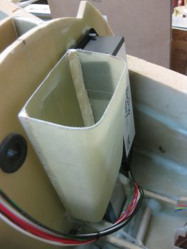
As my last officially task of the night, I dug the foam out of the tool box that I had used for a form. And then I cleaned up the inside just a bit.
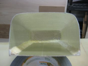
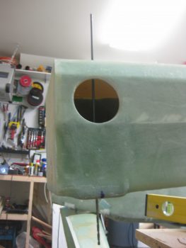
Then of course had to mock it up for a trial fit.
Here’s another shot of the nose tool box mocked up in place!
Ok, so tomorrow I’ll start leveling the wings and the CS spar to get them pretty darn close to perfect. ONCE that happens, I will then start drilling the CS spar/wing bolt holes into the wing & CS spar!