
I started off today right where I left off yesterday . . . drilling, drilling, drilling, drilling, and then drilling some more. Let’s say about 5 hours total today, with over 2 hours last night!
Yep, I was one of those builders who used the plan’s spotface tool to drill this sucker out. I can say now that it’s over that I’m glad I used it, because the holes are perfectly round and beautiful! That being said, if I knew of another really good way (yes, I’ve read about modifying hole saws, reamers and the like, but I went with with the spotface tool… Ironically because the 5/8″ bi-metal hole saw bit I ordered didn’t arrive in time! ha!)
One of the main reasons it takes so long to drill these holes is heat management. Yes, it may be a lot better with a different cutting/drilling tool, but with the spotface tool I would drill for 10-15 seconds, blow compressed air into the hole for 20-30 seconds, and then (starting today) wet it down thoroughly with cold water from a water bottle sprayer. These holes definitely get hot, especially due to the torque! And this was even more pronounced the deeper into the hole since the entire side of the spotface cutter was contacting the sides of the hole. Tons ‘o heat generated in this endeavor my friends! In fact, my cordless drills were struggling when I started out using them (my corded drill was buried away in my shop) and I even smoked one after pushing it too hard… even though I was rotating through 5 different cordless drills! And let me state for the record that the newer generation Ryobi Lithium batteries are a joke, many of them could barely make it through a couple rounds of holes.
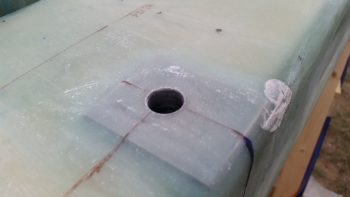
Nonetheless, I eventually got the holes drilled! Whew! What a feeling . . . especially when they land in the right spot! Below is the first light at the end of the tunnel I saw late this afternoon.
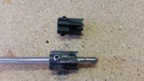
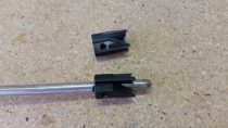
Luckily I bought another spotface from McMaster-Carr before I started, because the original one I had was worked HARD! The swapping of the old to new spotface was a bit of challenge unto itself. I had to drill out the set screw that was covered over with metal, and then the spotface didn’t want to come off the guide, as if it were welded in place. I eventually got it of course, but not without some wailing and gnashing of teeth!
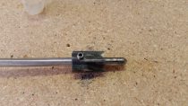
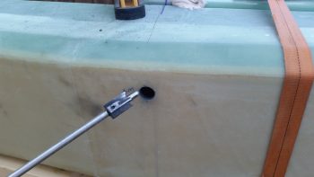
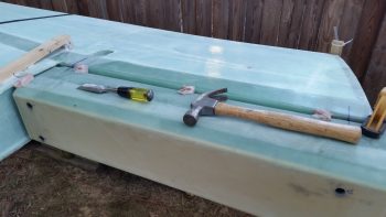
Here’s a staged photo showing the spotface just about to go in and do some real damage!!! Ok, maybe just a little bit of damage . . . ahem.
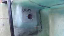
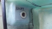
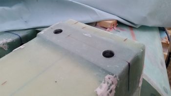
And here’s the other side. I took this shot to show all the layered extrusions that make up the inboard hardpoint on the wing (this pic was taken later after I pulled off the CS spar).
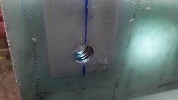
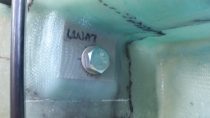
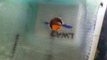
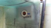
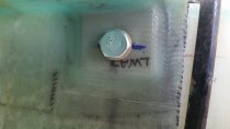
As I drilled out the inboard wing root bolt hole channels I cleaned them up and then test fitted an LWA9 bushing into the hole to see how it fit. The LWA9 bushing fit perfectly in each side. I then slid in one of my test bolts just to see how it would fit as well. With the bolt I was specifically curious to see its spacing since my hole is actually a hair low on the extrusion. But as you can see, there’s plenty of “meat” below the bolt to hold it in place. I have no doubt these hard points are 100% the strength of what they should be.
In the pics below, the top row is the right wing root and the bottom row is the left:
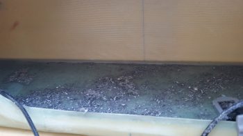
Below is the after affects of drilling out the inboard wing mounting bolt holes. Since I was using both air and water to clean out & cool the holes, it created an “aluminum soup” on the inner floor of the CS spar.
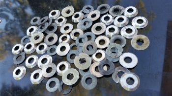
Also, here’s my abstract airplane art shot that I took using all the extrusion rings that I drilled out during this very long process.
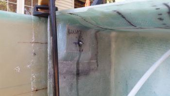
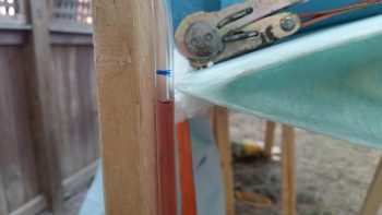
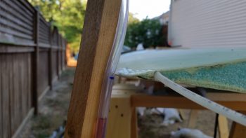
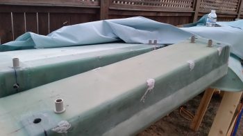
I also wanted to document my water level marks for each of the points of the wing that I was checking. The blue lines you see on the tubing are marked for waterlines other than the 17.4 WL.
Below is the inboard TE of each wing at BL 23. Since this curves up just a tad to intersect the cowling, according to plans it’s at WL 17.5. Just as a note, the distance between my two inboard TE corners was exactly 46″…. I like it! Also note, that although the levels at the following points may not be aligned perfectly with the water line (or the blue line), they are very close and also match pretty darn symmetrical between right & left wings.
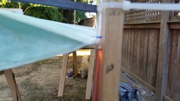
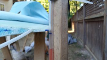
Here’s the outboard TE at BL157, with the right wing in the top pic. Since the wing slopes as it goes outboard on the TE and down from TE to LE, this WL sits at 18.35 (again, the blue line). So even though these look terribly high compared to the actual reddish water level line, they are within about 0.1″ off from being spot on. Another point I need to make is that the red water level fluid is a bit low after sitting out all night long (you can really see this in the pics above since the blue line is a bit farther off than 0.1″).
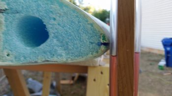
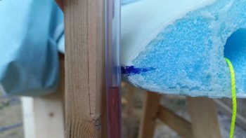
Finally, the outboard LE at WL 17.4, which of course is the water line for the entire leading edge.
After rechecking and verifying my water level marks, it was time to remove the CS spar from the wings (aka “Bondo Destruction Time”).
I removed all the bondo that I could get to on the top & bottom of the CS spar & wing junctions.
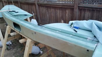
I then cracked the CS spar loose and turned it on its face. Then I got to work removing even more bondo.
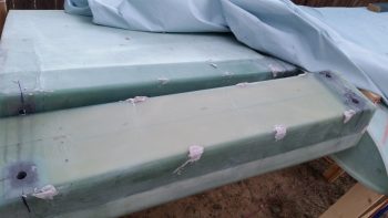
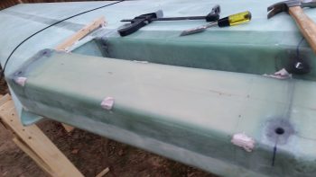
Here’s the right side of the upended spar requiring more bondo removal.
I also washed all the gray aluminum grime from around the bolt holes with Simple Green and was very happy to find no delams!
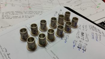
I then started work on the LWA9 bushings. I put them by their respective holes and marked them up so that they would match the depth of the specific hole they were being cut for. I then measured the depth of each hole using the recommended hole depth checker identified in the plans [NOTE: As I was cleaning up the next day I found a depth checker in the bag that the Cozy Girrrls shipped the LWA9s… oh, well! Just a point of note that if you buy these from the CG’s that it comes with a depth checker, so you don’t have to spend an extra 5 minutes making one!]
I then packed up all the tools for the night, and marked up all my LWA9s for trimming.
Tomorrow I’ll trim up all the LWA9s and then mount them in the spar & wing bolt holes with flox… and my temporary wing bolts.