
First off, as per plans I let this the engine mount extrusions cure until late afternoon to ensure a complete curing of the layup.
I then cleaned up all the excess glass with the Fein saw and really gave both side layups a good sanding.
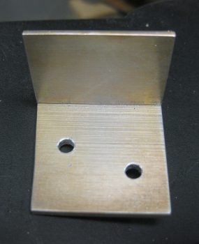
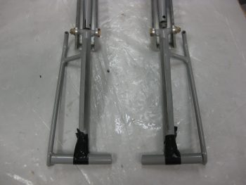
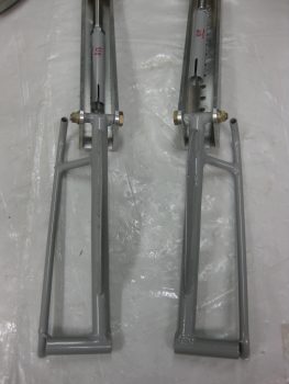
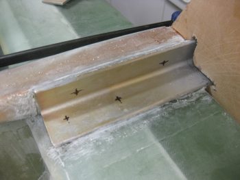
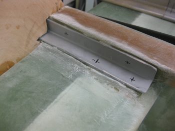
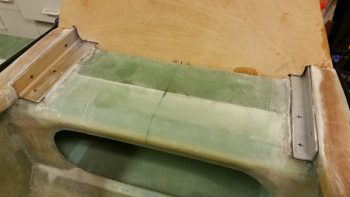
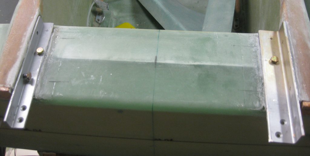
One reason I went with 4130 steel on the left side extrusion is that I wanted a higher strength extrusion than stock due to a much heavier and more powerful engine. But I also wanted a low profile extrusion on the left side, since that’s where the passenger enters. I understand it’s back on the spar and out of the way, but I did want no more than an inch high extrusion on the left side.
On the right however, where the canopy is, the extrusion is 1.25″ high. The base leg is even wider at 1.5″ wide. The upper right extrusion is of course 2024 Aluminum. I pretty much left the thick pad of glass that I laid up between the right side extrusion upright and the longeron at the same 1.25″ height as the vertical extrusion leg, but I did taper it down into the longeron surface. Still, the glass under both these upper extrusions is thick, stout & strong!
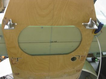
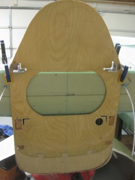
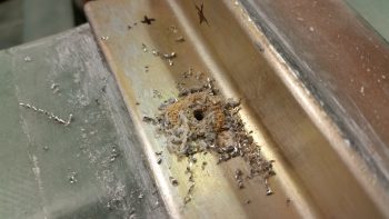
I then cut the pass through holes on the firewall for the engine mount extrusions. I figured I would have to open up those pass through holes a bit, but it was really tough getting the firewall on. And although I checked the lower longerons to see if anything was messing up the re-mounting of the firewall, I couldn’t see anything.
I opened up the holes based on what I thought was some binding, but I was bamboozled by the firewall in that the real problem was at the bottom, not the top. Since the bottom longerons (or stringers) curve upward, then a bit more needs to be removed from their mounting holes to install the firewall with a straight in motion.
The next issue I encountered was the right engine mount extrusion 1.6″ bottom reinforcement & connecting plate. Since it matches the 1.5″ width of the upper right side extrusion, and due to the slight angle that the extrusion is mounted to the longeron at, I simply just could not get the screws mounted into it because it kept hitting the firewall. Obviously, this clearance issue will only get worse when the Fiberfrax and Stainless steel final cover is added to the firewall.
So I marked a slight angle on the forward side of the 1/8″ reinforcement plate (it’s still attached to the outer angle that the engine mount tube is attached to).
I then trimmed the edge using the Dremel Tool (and a face mask of course!).
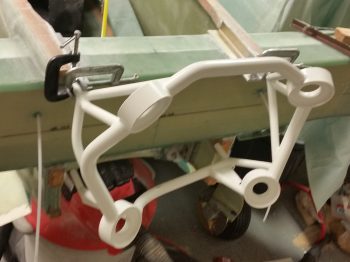
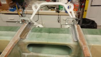
I then was able to get the upper engine mount extrusion assemblies installed, and then clamped the engine mount in place.
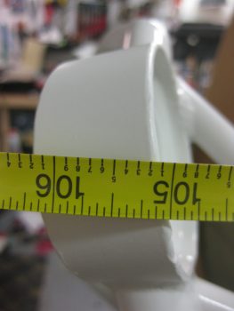
By trimming the top engine mount posts by 0.32″ I am now able to easily attain the 134.2 fuselage station at the top aft engine mount ring. I added a pic of the engine mount post so one can get an idea of how it will look bolted in place.
I then focused on the lower engine mount posts for a bit.
The extrusion pass through holes needed to be modified just a bit, so I marked them up.
After mocking up the fuselage, it was clear that the lower engine mount posts were going to need a trim as well. There’s no room for them and currently they would have to stick into the firewall for the bottom engine mount rings to be at FS 134.45. I knew I was going to have to shave another 0.3″ off of each one.
I pulled out my Harbor Freight “Dremel” tool and realized the cutting wheel was pretty small and needed to be replaced. Well, not wanting to waste it, I decided to cut some fairly thin tubing by lopping off the offending inboard rudder pedal tubes from each rudder pedal.
The Dremel made short order of the offending rudder pedal cross bar.
I then remounted the rudder pedal. You can see how way much more room I have with that inboard part of the cross-tube gone!
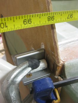
I then removed what was left of the small cutoff wheel and replaced it with a brand new one. Then I got to work trimming 0.3″ off of each lower engine mount post.
Here’s a shot with the engine mount post trimmed to length (minus 0.3″).
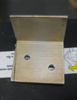
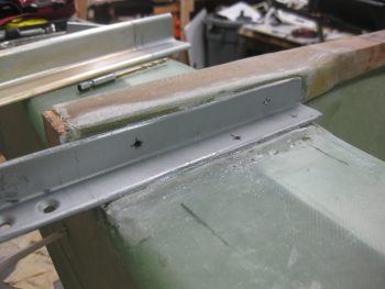
I set aside the trimmed engine mount & marked up the upper engine mount extrusions to be drilled in order to receive 1/4″ AN4 bolts. Below is the right side with its drill bit holes marked.
I then did the same for the left side.
And here’s a shot of both sides . . . Ok, ready to drill!
I started drilling the right extrusion first. Of course drilling straight down on these holes doesn’t present any real challenges . . .
But Boy, drilling the side holes sure do! I used a flexible drill shaft that I picked up from Home Depot a while back specifically for this purpose.
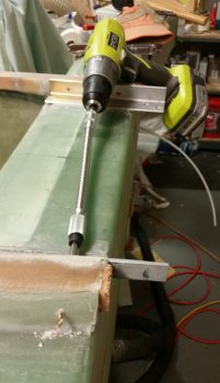
I focused on the left side 4130 engine mount extrusion because if anything is going to tear up my drill bits, it will be this hard tough stuff (although its not anything near as bad as stainless steel!)
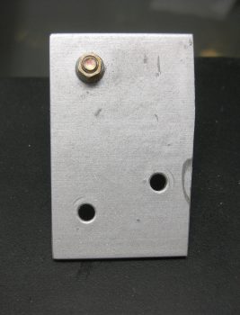
I rounded up some AN4 bolts and fit-checked the bolt holes. Nice and snug!
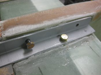
It got pretty late, so I needed to stop drilling for the evening, but here’s a shot of both sides with the their one bolt each installed.
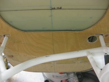
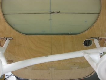
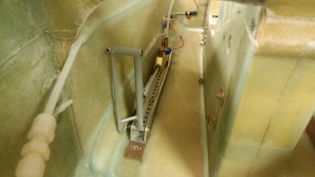
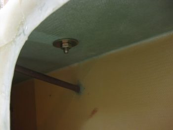
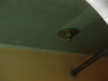
Finally, here are a couple pics off the top “ceiling” of the interior CS spar showing the nuts and large washers holding the bolts in the extrusions in place. I am happy that my Spruce hardpoints embedded in the CS spar are in the right spot and that I’m hitting them with my bolts!
Tomrrow I’ll continue to work on the engine mount, the extrusions and the firewall, and of course I’ll continue to post my progress here. Either tomorrow –or very shortly thereafter– or the next day I’d like to have the engine mount, et al, in the bag in order to move back onto the wheel pants.