
It was a light build day since I had a bunch of errands to do today plus get ready for a birthday party tomorrow.
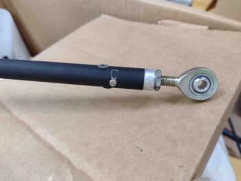
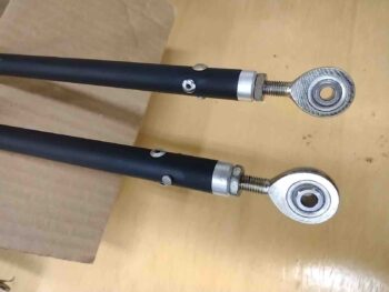
I did break out the control tubes to touch up some paint on a few significant scratches I made while installing the rivets. Here’s just a couple of examples of the scratched paint.
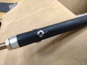
Although I want the control tubes looking as spiffy as possible, within reason, my overarching concern is corrosion. I picked up some flat black enamel last night that will allow me to simply brush the paint onto the damaged areas without everything else getting obliterated with black paint as well, as it would with a spray can.

Here are some of the previously scratched/damaged areas of the control tubes now touched up with black, a few hours after I painted them. Tomorrow, after a good night’s cure, I’ll tape up the rod-ends and then clear coat the black paint on the control tubes.
My next task was continuing on in my quest to get as many winglet-securing UNI plies of glass cut out of my scrap bin as possible. I also finished off the remainder of the UNI roll since I have a good bit coming this Wednesday, mainly for the strake top layups.
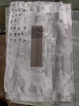
Here’s the winglets’ UNI ply schedule as spelled out in the plans:
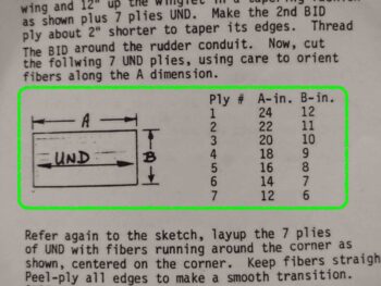
And here’s my UNI plies count for the winglet UNI schedule, above. As it stands, I only need 3 plies to have all the UNI cut and ready for laying up to secure the winglets to the wings. My next task will be to review and possibly cut the BID plies required for these layups as well.
After I finished up this blog post and published it on my website, I then reviewed the plans for the winglet installation on the end of each wing. I was focusing on the point that the plans use as the epicenter for all the dimensions , which is the inboard/forward corner of each wing’s aileron cutout: WPRP.
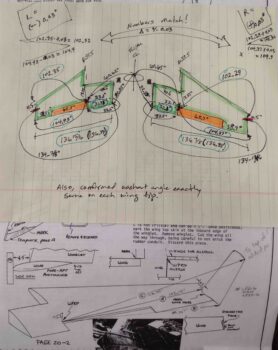
My concern was that I knew my wings weren’t exactly equal in length and moreover, that there was a slight difference in the distance inboard from the wing root edge where the ailerons start (1/8″ to be exact). Yep, this was not going to allow me to sleep, so well after midnight I opened up the shop, fired up all the lights and started measuring every dimension on the wings and ailerons I could get my hands on [twice, just to make sure my numbers were right]. These convoluted chicken scratchings are what I came up with:
So buckle up buttercup and put your thinking cap on!
FINDING: My left wing is nearly 1/16″ longer than the right, actually 0.06″ to be exact. And this is proven out In nearly every dimension measurement I took. Interestingly, the most egregious error I have is that the wing TE is 31.98″ from wing root corner to aileron cutout on the left wing, and 32.1″ on the right wing: 0.12″ off, or again, 1/8″.
However, go forward to WPRP and measure straight to the wing root edge (~5.75″ forward of TE), and both wings are at exactly 33.1″. In fact, in each wing’s inboard square “box” between WPRP, the corner of the BL 55.5 wing notch (end of CS spar), the inboard forward wing root corner, and the inboard aft corner of the wing root edge, nearly every dimension is exactly the same between left and right wing. This means that my ailerons inboard edge are most likely at a very slightly different angle to each other combined with my wing to aileron gap slightly different as well…. something is going on at the inboard aileron TE since the WPRP ‘epicenters’ are pretty much in the exact same spot on each wing.
As per the Chapter 20 plans, I then marked a line on each wingtip that determines each winglet’s LE when setting the winglets on the wing and also determining the winglet cutout at the end of each wing (see bottom part of pic above). This line is 4.5″ aft of the wing LE. From there, I checked the bottom 2 critical measurements as basically outlined in the plans: WPRP to the 4.5″ line, and WPRP to the outboard TE corner, Again, these dimensions confirmed that my left wing is exactly 0.06″ longer than the right… at least from WPRP to the winglets.
My initial thought at 0100 in the morning was that I had two (2) options:
A) Simply mark and sand down the left wingtip 0.06″, or
B) Simply divide the difference in half and add it to the short (right) wing and subtract it from the long (left) wing. Problem solved.
But back in the house, after taking another good look at the plans, I realized that the plans “A” dimension (WPRP to the 4.5″ line) of 102.15″ was shorter than both my left (102.35″) and right (102.29″) wings “A” dimensions. I was merely lopping off everything outboard of 102.15″ so who gives a hoot if the forward 4.5″ of my left wingtip is 1/16″ longer than the right wing? Do you think anybody will notice? Will it affect drag? haha (Sorry Burt, should’ve trusted you!)
Finally, I will note that I used my level to confirm that the washout angle at each wingtip matched each other perfectly… which gave me even more confidence that I should be good with my strake-to-wing interfaces as I do the final glassing on the strakes.
Tomorrow I plan on getting back to work sanding and shaping the right strake top in prep for glassing. I will also attempt to get the right fuel site gage LED light wires run “above ground” and install the right baggage area 3-LED light cluster as well.
1/16″ difference in the wings? Its time to let yourself off the hook and get a pat on the back for excellent and accurate wing making. I’d call that very good work. Your bird will fly straight.
Haha… thanks my friend! Only looked at all that since Burt called out accuracy down to 0.05″ during winglet install… a rare thing in these plans!