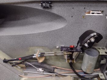
The gray granite interior paint needs to cure for 24 hours before getting clear coated as per the can, but I general start my cheating on that about the 16-18 hour mark. Regardless, I still had a fair amount of time until mid-afternoon before I could clear coat all my painted areas.
I spent some time dialing in the requirements for some extended lever microswitches for the AG6 annunciator warnings and panel on/off indicators, to be mounted both on the aft side (idle) and forward side (WOT) of the throttle quadrant. Since I need 2 separate circuits on each side, I doubled up the output of each switch and ID’d double DPDT micro switches so I only have to deal with mounting one physical switch each side.
In addition, although I was effortlessly able to run an added pair of wires to the upper sidewall, just under the longeron —where I added my 2-switch box for the GIB lighting circuit— unfortunately I was only able to run a single pair of wires to the canopy latch handle. I have two separate canopy open warning systems: one via the AG6 warning annunciator and the other via a pair of red & green LEDs on the panel + horn. I can’t piggy back off only 2 wires, so I had to add a DPDT relay into the circuit —controlled by this single pair of wires— that then acts as the respective individual microswitches. So instead of 2 microswitches, with only a pair of wires to work with, I will now have 1 microswitch and 1 relay to do the same job. This of course required ginning up the new circuits on paper before I could know what parts to order.
I submitted an order with Mouser for all these electrical tidbits and also an order with McMaster-Carr for the thinnest black phenolic they had for possibly attaching to the sidewall at the lower part of the throttle quadrant as a slick glide-plate for the throttle cable. I also picked up some 0.036″ stainless steel for the RAM air can open-close actuation lever, as well as some hardware.
With my parts ID and acquisition duties out of the way, I then spent a couple of hours on another sideline but required task —as I’ll reiterate I’m focusing on the left sidewall components (from panel aft) for a few days as I get the throttle quadrant installed… simply to knock out the last vestiges (at least a good majority) of cockpit components as I work my way back to the engine. This will leave pretty much panel forward to contend with when engine, cowlings and micro-finishing have been completed.
I digress. Back to the task at hand: I’m creating yet another storage compartment —much like the GIB right armrest storage— in the remaining aft area of the front left armrest. Under the armrest I only have 3 micro-actuators remaining to mount for the Oil heat valves and after assessing the space requirement for these, I designed a storage compartment to fit the remaining upper aft area of the pilot left armrest.
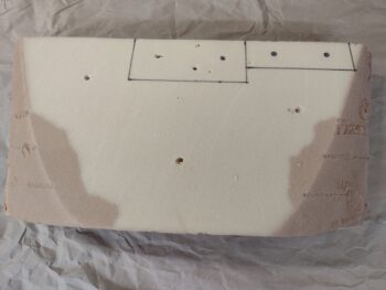
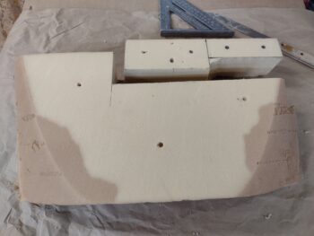
I grabbed the big urethane foam block I had used for the aft nose & avionics cover mold and took off the top couple of layers. That gave me a nice flat canvass to draw out my next masterpiece… ha!
I know it’s hard to tell the actual size of this thing: it’s 12.5″ long by 2.3″ wide. The front 6″ is 2″ deep while the aft 6.5″ is 3″ deep. The different depth areas will be separated by a vertical divider to make two separate compartments. Yeah, not a ton of room, but definitely enough for pens, eyeglasses, spare batteries, fuses, etc.
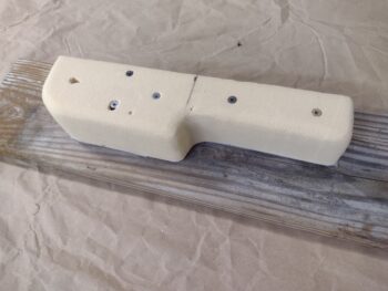
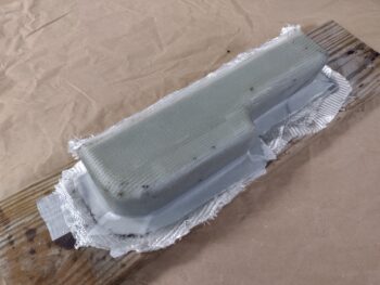
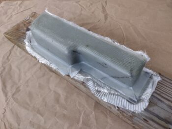
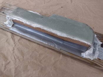
After extricating the foam I needed for my storage bin mold, I cut it to its 2.3″ width (a hair under allowing for glass thickness) and mounted it on its side on a length of scrap wood… below is how it will look mounted on the sidewall.
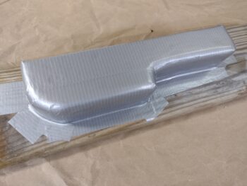
I then taped up the foam mold…
And glassed ‘er up. I actually covered the entire mold with peel ply first, before I started laying up glass.
All with scrap pieces of BID. That being said, I had enough scraps to do one full first ply. Then scraps for the next 1-2 layers (there’s overlapping plies here and there) and then one final large ply on the outside.
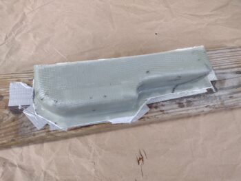
I peel plied just along the exterior mounting flange to allow laying up a BID tape around the edge when I install this in place in the cockpit.
I few hours later, while the glass was still somewhat pliable, I did some gross razor trimming around the edges. I then left it to cure overnight.
Towards the latter end of my left armrest storage bin mold making I clear coated the interior paint on the left sidewall in the nub vicinity. I also clear coated the inside of the cup holder.
By the time I finished glassing the storage bin with another hour of messing about on securing the throttle and mixture cables in the backseat area, the clear coat was cured and I could then proceed with the installation and testing of my throttle handle and quadrant. BTW, I’m happy to report my center-routing of the throttle handle electrical cable is working a treat and I have no more clearance issues with the cable. I can now put that issue to be bed… so on to the next issue!
With my throttle and mixture cables secured into position from A-Z, I could now proceed with dialing in the operations of the quadrant handles to match the rotation of the respective levers on the fuel injection servo. I spent over a good hour first on the throttle and got it close on each end, about an 1/8″ gap, without full pivot at the quadrant… while the fuel servo throttle lever was rotating stop to stop.
I took a break from the throttle handle and worked the mixture side, and was pleasantly surprised to have that dialed in within about 20 minutes. The quadrant mixture lever pivots from aft stop to forward stop matching the fuel servo mixture lever doing the same. At least one thing was easy on this thing!
I then messed around with the throttle lever for another good 45 minutes while trying my best to assess the nuances of how this geometry is playing out. I’m thinking the hole on the throttle lever may need to be set just slightly lower… but I decided to stop for the night and re-engage on this issue tomorrow…
And with that, I called it a night.

