
I started off today spending well over an hour assessing and updating circuits in my electrical diagrams. Specifically those involving reporting from microswitches, relays and switches to the AG6 Warning Annunciator and instrument panel notification lights. Over the years, I’ve updated/bought various components and not all my diagrams were annotated to reflect these changes. For now I’ve chicken scratched in new circuits that reflect what they need to be… a couple of them I need to bench test to verify my circuit logic is right.
Out in the shop I removed the front left armrest storage compartment shell from its form.
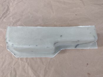
I pulled all the internal peel ply, cleaned off the peel ply boogers and cleaned up the edges a bit to test its fit on the cockpit left sidewall.
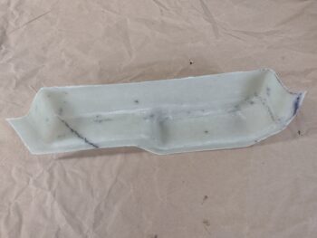
At first it seemed like it might be significantly too tall and too big to fit, but I double checked it inside the armrest and it just fits. Good thing, because although the dimensions don’t scream tons of storage, this will provide a good bit of it for a fair amount stuff. And that’s always a good thing!
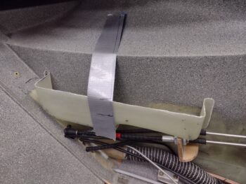
I temporarily put the armrest in place and marked the top of it with tape along the sidewall so I could fit this compartment in place. I had already did a few rounds of trimming the outer flange by this point.
I designed this storage compartment to interface with the armrest in kind of a unique way: about 1.5″ on each end will actually sit under the armrest top while the hatch will open over the center 10″. That means I’ll leave the center 10″ close the height shown here so that it sits 1/16″ below the top of the armrest as a lip for the cover to rest on when closed. Conversely, the height of each end —fore and aft— will get trimmed to fit under the armrest top… note the initially marked cut lines for the forward and aft section trim areas below.
I of course assessed the fit of the bottom side of the storage compartment as well. It was here that I determined that I needed to change my thoughts on how to mount this thing. I had originally planned to flox it into place with a single ply BID tape around the edge to secure it to the sidewall. However, if I ever need to work on or replace any of the throttle/mixture cables I would be cutting this storage box out or working around it. Too much of a pain. In addition, making it removable will allow me to take it out when installing the 3 micro-actuators for the oil heat cables.
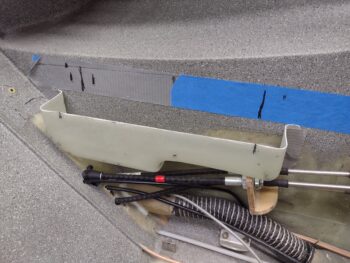
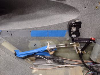
Thus, I determined it had to be removable. After looking at it a bit more, I developed my plan to mount it: 1 Clickbond near the bottom center and 4 RivNuts… so 5 hardpoints for mounting total.
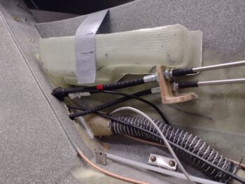
This shot below shows a few things. First, note that I sanded the top of the sidewall cable bracket level to remove a bit of material to provide more room for the storage compartment to sit level, and slightly lower.
Second, I drilled a 3/16″ hole into the flange on the bottom edge of the storage compartment, taped it up and inserted a clickbond into the hole. I then floxed up the clickbond and used a spreader clamp to secure the storage box with clickbond into place on the sidewall. While the flox cured I got to work on my next task . . .
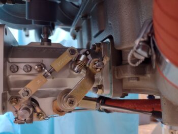
I spent a good 30 minutes trying every configuration I could conjure up on the front and aft throttle cable rod ends to get the lever movements matched between quadrant and servo throttle levers. I even drew up a truth table (another one!) to assess the contra-opposed actions of these rod end positions. My analogy to describe this is simple: You have a large workshop that has 2 light switches for the shop. You need all the lights on, but each time you flip one light switch on, it shuts the lights to half the shop off. The switch actions are opposing each other in the same way moving a rod end will give you the desired effect in one manner, but a totally opposite negative effect in another manner (i.e. closer or farther from the servo idle hard stop while creating a larger gap between lever and quadrant stop on the other end).
Clearly a variable needed to change. That wasn’t going to happen at either the servo or quadrant side rod ends as I had exhausted virtually every configuration. My end result always turned out with full movement at the servo (which is good) but with about a 0.1″ gap between the throttle lever and both the front and aft stop in the slot on the quadrant, respectively. If I got the lever to either stop at the quadrant, it invariably meant that I wasn’t getting full rotation at the servo. I needed just a hair more movement in both directions (push & pull) to get the lever to the quadrant slot end stops.
When I machined this new throttle handle lever, I added another hole for the slaved GIB throttle. This hole sits nearly 0.5″ below the upper hole, so there was plenty of meat in between those holes to drill another one… which is exactly what I did. I split the difference and drilled a 3/16″ hole right between the existing holes.
I then tested out my new throttle lever cable attach point. Bingo! Within 15 minutes I had the throttle cable dialed in so that with the quadrant throttle lever forward at the stop, the servo throttle lever is at its WOT stop position. The same is essentially true in the aft idle position, as shown here, but I will note there is about a 0.005″ gap (1-2 pieces of paper thick) between servo lever and the idle stop pin. This means I’m hitting the quadrant aft stop just very slightly before the servo lever hits the idle stop… actually good both directions since it virtually eliminates any added force on the servo lever or cable connect rod. Moreover, I can always do some judicious sanding at the quadrant to remove a few thou to match these if need be.
With the throttle cable finally dialed in I went to dinner with Jess to celebrate. Upon returning back home we went out to the shop where she helped me mix up epoxy and layup the BID on the floxed in place sidewall clickbond.
We then left the peel plied clickbond layup to cure overnight and called it a night.