Since I know I’m off my engine removal schedule by a day or two, while I await the fittings to finalize the fuel/oil lines I worked on something that I want to get done as a self-perscribed prerequisite to drilling the 3-1/8″ hole in the firewall for the RAM air canister: mounting the ANL40 fuse link and base.
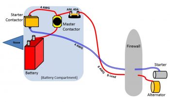
If you recall, after much consideration I modified my starter and charging circuit design by separating out the B-Lead into its own dedicated cable and by moving all the associated components to the nose-located battery compartment as such.
However, even though this configuration has been implemented successfully (reportedly), I was never too keen on the ANL40 being so far removed from the line it was protecting. I chalked it up to 2 things, made a mental note to assess it, and then pressed on. Those 2 things were that A) Again, its working in a real-world install, and B) 10 feet is not a huge distance to electrons that travel the speed of light.
However, as I pointed out a couple of days ago, Bob Nuckolls reminded me of a core principal that I was not following in regards to my ANL40 Fuse Link location when he stated, “Recall that circuit protection is for WIRES . . . and that the protective device is installed as close as practical to the SOURCE of energy that puts the wire at risk.”
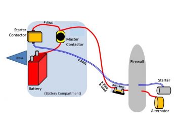
Again, as a result, my ANL-40 fuse link is going back on the firewall, on the hell hole side. However, instead of employing a 1/8″ thick x 1/2″ wide copper strip, I went with my optional configuration and am using 8 AWG cable to connect the forward (hell hole) stud of the Blue Sea terminal to one side of the ANL40 with the GRT EIS HALL EFFECT SENSOR placed in-between, then run the B-lead from the ANL40 forward to the battery contactor. Therefore, my new starting & charging circuit configuration now looks like this:
My 2 goals for the day were to install both the ANL40 base, fuse link, etc. and the GRT EIS Hall Effect sensor.
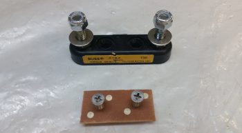
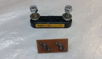
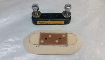
I started by ginning up a phenolic nutplate assembly with the same #10 screw pattern as the ANL40 base. Since the fuse link sits in the middle of the 2 posts on the base, the only screws that can be used are countersunk screws. Since I’m mounting the unit on the front face of the firewall I clearly can’t put nutplates on the aft firewall face, so I had to go with a in-Hell Hole surface mount solution.
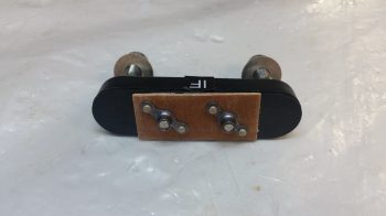
Here’s the aft side of the ANL40 nutplate assembly.
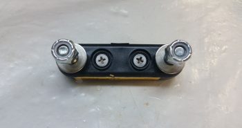
And a couple shots of the nutplate assembly installed on the ANL40 mounting base.
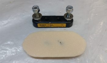
To embed the nutplate assembly onto the forward firewall surface in the Hell Hole, I made a mounting pad for the ANL40 mounting base from 3/8″ PVC foam.
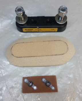
I then carefully carved out a notch for the nutplate assembly in the foam mounting pad.
Here’s a bottom shot of the foam mounting pad with the nutplate assembly installed.
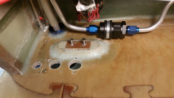
I then used 3 plies of glass (BID/UNI/BID), prepregged, and glassed the ANL40 foam mounting pad with the nutplate assembly flocro’d into place (with all the typical pre-work: micro-ing foam, etc.). Again, the mounting pad was glassed onto the forward side of the firewall in the hell hole.
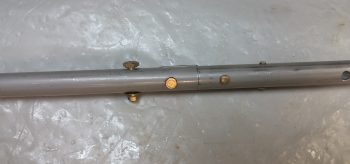
Off topic a bit here, but as the layup above cured, I decided to finish off the elevator control rod by drilling a #10 hole and mounting an AN3-7A bolt into the hole (IRRC this is a Ken Miller mod….). The bolt will be in addition to the clevis pin that secures the forward side of the elevator control rod to the aft side.
A few hours later I cleaned up the cured layup (yes, I used fast hardener) and test installed the 2 ANL40 base mounting screws. I also trimmed the glass overhanging the existing firewall electrical package component holes and redrilled the upper holes for the mounting screws.
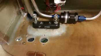
I then mounted the ANL40 base into place with the 2 countersunk screws.
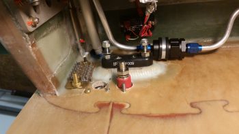
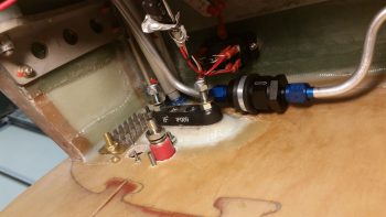
And remounted all the firewall electrical package components (again, except for the ANL40, these are all temp mounts until the Fiberfrax and 6061 aluminum firewall cover are in place). I uploaded both pics of this since they show a bit different viewing angles.
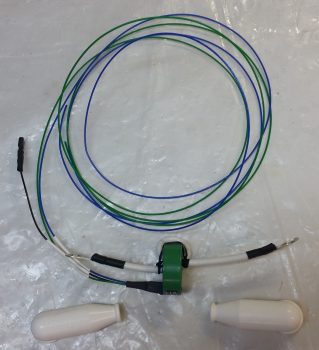
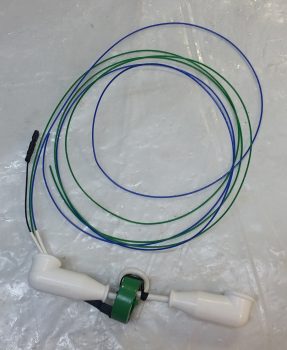
Being able to get a feel for the space between the Blue Sea B-Lead connector (it’s red) and the ANL40 base, I then got to work finalizing the GRT EIS Hall Effect sensor configuration. I trimmed the long 8 AWG wire and terminated the Blue Sea connector end with a 3/8″ terminal. I also labeled & trimmed the ground wire, then terminated it with a Fast-ON PIDG terminal.
I slipped on the white rubber boots, and Voila! Ready for install.
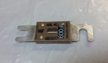
Since I’ve had the actual ANL40 fuse link for a number of years, there was a bit of tarnish on the metal blade connectors so I used a Scotchbrite pad and some white vinegar to clean them up a bit.
I then installed the ANL40 fuse link into its base, on top of the glassed-in foam mounting pad (with the embedded nutplate assembly) and then got busy connecting all the cables to their appropriate mounting lugs.
I also co-ran the red 14 AWG SD-8 backup Alternator power feed wire through the GRT EIS Hall Affect sensor a couple of passes (both the primary alternator B-Lead and the SD-8 backup power feed get passed through the Hall Effect sensor twice to place the readout scale on a 0-50 Amp scale vs a 0-100 Amp scale… the latter which I don’t need since my primary alternator only puts out 40 Amps max).
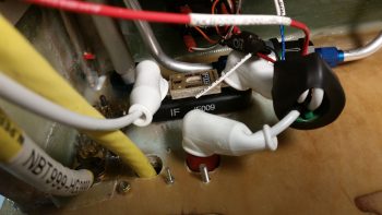
The route of the electrons is this: Alternator current runs via B-Lead to the firewall side of the Blue Sea pass-thru connector (red fitting), then on the inside of the Blue Sea pass-thru a cable runs to the right post (in pic below) of the ANL40 fuse link VIA 2 passes through the Hall Effect sensor donut. Then, from the ANL40 left post (again, as depicted in pic below) an 8 AWG B-Lead cable carries the current up to the nose, connecting to the Master Battery Contactor (as depicted in my updated diagram way up there ↑).
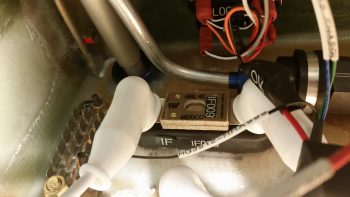
Here’s a closer up shot of the installed ANL40 Fuse Link.
In addition, you can also note that I used a decent sized piece of heat shrink to seal and cinch up all the wiring going through and wrapped around the Hall Effect sensor donut. It may seem like the Hall Effect sensor is left to sway to-and-fro in the wind, but with the robust 8 AWG cable securing it in place, and the amount of force I had to apply to get both terminal ends in place (not excessive, but it’s tight) …. that puppy ain’t budging!
Another angled shot of the ANL40 fuse link for the alternator’s B-Lead feed and the GRT EIS Hall Effect sensor . . . plus note the additional “big” wire runs that are deemed big enough to hang out and traverse the fuselage with the big yellow cables.
And a final parting shot for the evening.
Tomorrow I’ll continue to work my tail off to get all the engine & firewall components/hoses installed, ID’d, configured, and/or mounted AND data collected before I pull the engine off the fuselage. [I will note that I baked 2 batches of pinkish colored desiccant to refresh the engine dehydrator].
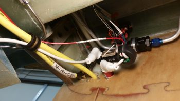
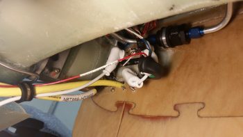
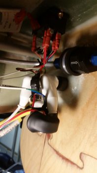
Great work as usual. Given you are also having a second alternator, an SD-8, are you also doing something similar on the B lead with an ANL link, or given the lesser amps, just going for a regular fuse? If so, is this at the firewall or considered acceptable up near the nose?
On the SD-8 there is no ANL Link. There is, however, actually two fuses… both inline ATC types (as per Bob Nuckolls). One fuse is very close to the SD-8 PM alternator output (15A) and then the other is a 30A inline fuse near the master contactor, that Bob not only deems acceptable in the Z-13/8 architecture but denotes that it should be no less than 6″ from the master contactor connection.