
Yes, today was another blitz of CAD work and 3D printing. I started by spending a good hour creating my own design of a throttle friction lock knob since I couldn’t find any that I had on hand or online that I liked. Since the throttle friction knob will be below the top of the armrest in its curved (following the pivot path) pocket, I need to be able to get my finger in to “dig it out” when it’s positioned at either end stop of its pivot (i.e. fully unlocked or fully locked).
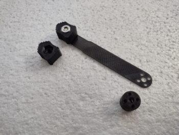
Once my knob was designed (4 versions until final) I then broke up the singular throttle friction lock lever and standoff nub (that both engages in the locking action and positions the handle & lever at the correct left-right position) into two pieces to be able to make this thing.
Yes, I could machine this thing out of one piece of aluminum, and it would be much sexier, but that’s a fair bit of time and a lot of wasted aluminum stock for something that you’ll only see the top 1″ of when it’s installed. I have a 2′ x 2′ x 0.04″ thick aluminum sheet that I’ve used just a fraction of on hand that is perfect for this, as well as 5/8″ round stock that will serve perfectly for the standoff nub. Top that off with some AN-numbered CS 4-40 screws and we’re in business for separate components to be assembled to create this kit.
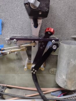
Before I got to actually making this thing, I of course had to test it out. I’ll point out that in replacing the short stock lever which can of course rotate virtually 360º as it tightens or loosens (of course normally it would be a much less wider range) I am limiting myself to a certain window of that pivot action, which will require more pivot space as I move farther from the pivot point.
In short, my planned corner pocket on the armrest for this thing was going to be about 1/2″ less than the length of the throttle quadrant plate… after playing around with the throttle and mixture friction lock mockup, I’ll be making the pocket at least as wide (or long) as the throttle quadrant top plate. That being said, the friction lock is working spot-on for what/how I’ve designed it thus far.
I’ll note quickly that I also did a final 3D print of the front corner heat sub-panel cover. I hit it with a couple coats of primer and a few coats of black paint. I was “baking” it under the heat lamp and totally forgot about it until I was writing this blog post… pics will be forthcoming tomorrow.
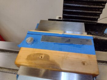
I then cut out a slice off my 0.040″ thick aluminum sheet and used my new painters tape and super glue method to hold it in place. As I was putting the clamps on (not the one I usually use btw) the plate slipped of the 90º mark I had made. With the quickness of how the super glue cures there was no getting back onto the line, without redoing the whole process.
I widened the probe points thinking this would take this slight pivot into account, but I need to be much more specific in my probing method for the system to “know” that the stock to be machined is off kilter.
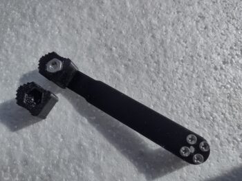
The nub off to the left was a test to see if it would hold during drilling ops, since I wasn’t doing any machining on this piece… just downward rotational forces, no side loads.
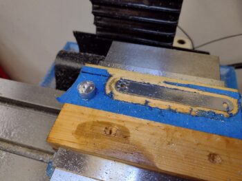
Well, my off kilter stock didn’t get the attention required along the top (far) side since the probing method I chose in my ever-present haste didn’t account for it. More lessons learned for me. The end result is that it has a bit less material on that side, but still enough for the small 4-40 screws to hold fine. It’s ugly, but functional. I’ll use it for now and remake it later after the bird is flying… unless something configuration, design or operational-wise requires it be remade sooner.
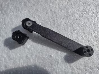
Note the standoff nub made it through the first round of hole drilling prep. It faired decently until the very end of the 3/16″ hole getting drilled in the middle. Towards the end the rotational force overcame the holding power of tape and super glue and the nub decided to hitch a ride with the drill bit. No big deal… I learned something and finished the holes on the drill press.
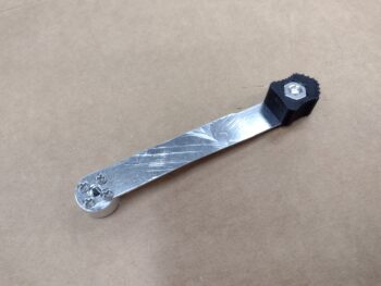
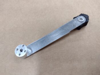
Still on the standoff nub, after I drilled the holes I then thread-tapped the center 10-32 hole and the four 4-40 holes before assembling it all together. Of course the 4-40 holes and the 10-32 hole at the top all got hit with countersink bits for their respective CS screws (The marks on the aluminum are from getting a thin scraper under it to pop it off from the tape/super glue).
Here we have the functional throttle/mixture friction lock handle.
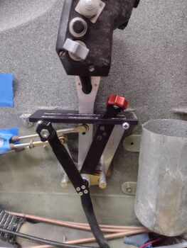
I then did an ops check with the new throttle friction lock handle. It worked a treat just like the 3D printed mockup that I tested. Again, the throw from one end to the other will be a about 0.5″ to 0.7″ more on each end than I had planned for, but that doesn’t present any issues that I can note.
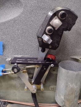
I took this shot specifically to show the handle heights between throttle/mixture friction lock, mixture handle and the throttle handle above all of them. Again, once the friction lock handle is about 1/4 way forward or aft from center it starts “submerging” below the top surface line of the armrest.
As I had mentioned in yesterday’s blog post, I had wanted to get to work on the initial armrest configuration for the interface with the throttle friction lock, but as par usual time got away from me and this is it for the day. Tomorrow I’ll focus on the cutting and reconfiguring the armrest to allow for a corner pocket with slot for the throttle/mixture friction lock handle/lever.