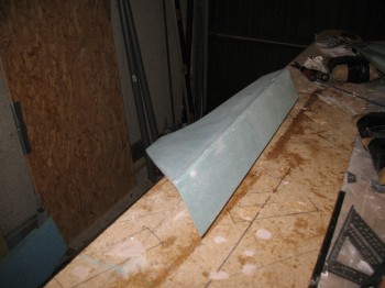
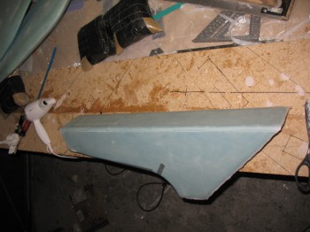
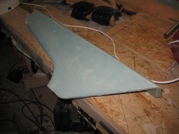
I actually started today by popping the lower winglets off of the wood blocks that they were bondo’d to. Then I chiseled a bunch of cured bondo off the winglet surfaces.
I then marked, cut & sanded the TE of both lower winglets.
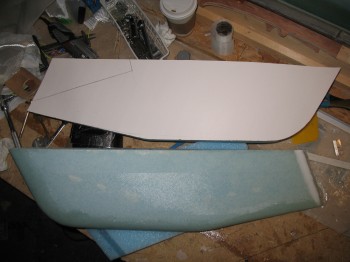
 I then measured, marked & cut the foam I had micro’d to the front of the Right rear armrest console.
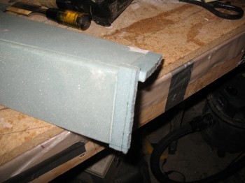
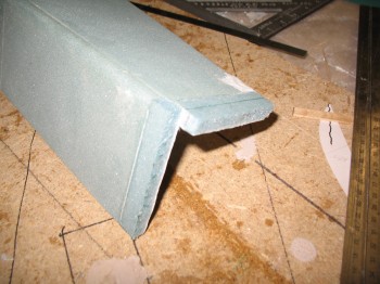
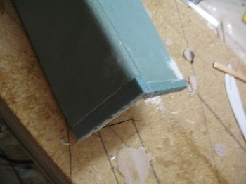
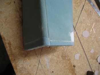
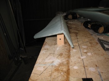
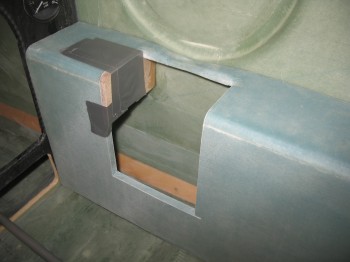
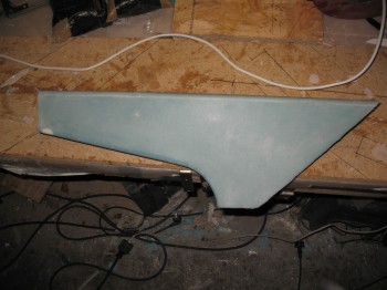
Once I had cut the Rear right armrest to the correct length I shaped the corner by rounding it over to match the existing corner radius. I also radiused the bottom edge of the armrest as well (including the white micro repair patch).
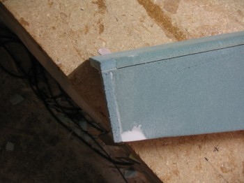
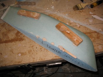
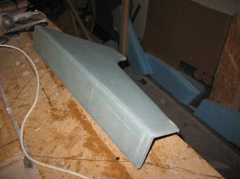
I mounted a 2×4 on the workbench with wood screws and then bondo’d the armrest to the 2×4 to give me a nice solid, elevated surface to glass.
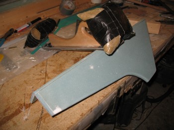
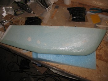
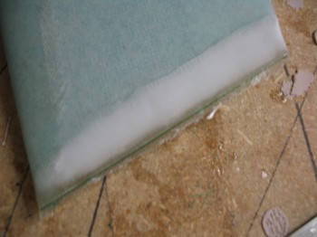
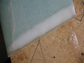
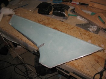
I mixed up some epoxy with fast hardener & made up some thick micro to fill the gaps & dings. I then covered the rest of the armrest foam with micro slurry. Once I was good to go with my micro prep, I glassed the armrest with 1 ply of BID. I of course peel plied it as well (as well as a little duct tape to hold the glass to the foam on the bottom edge radius).
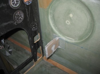
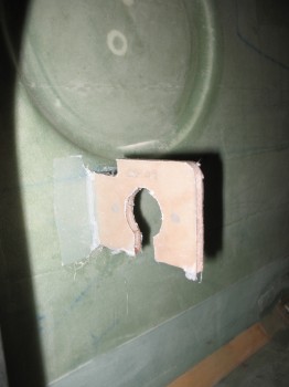
With the Right rear armrest BID layup curing I went to work on installing the front control bracket (CS109) for the flight control grip stick assembly onto the interior Right side of the fuselage. To start I had to mark & drill 2 each #12 holes into CS109 (Birch plywood). I checked the fit of the 2 bolts that will attach the control bearing assembly to CS109.
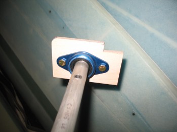
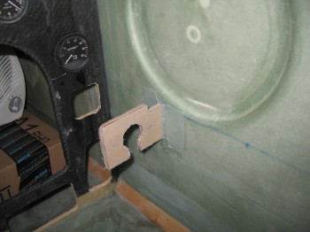
I then taped the control rod/bearing/CS109 assembly in position onto the Right front armrest console. Once I was sure that it was positioned correctly, I 5-min glued the edge of JUST the CS109 control bracket to the Right interior fuselage sidewall.
I waited a little while (admittedly more than 5 minutes!) & then removed the tape and the Right front console, leaving behind just the now attached CS109 control assembly bracket.
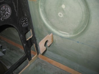
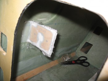
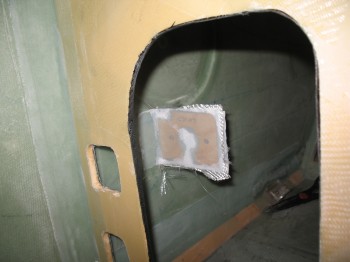
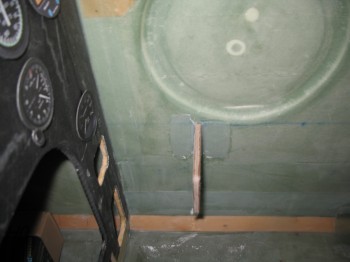
I then floxed filleted the corner between the CS109 bracket & the fuselage sidewall on both the fore & aft side of CS109. I glassed a 1-ply BID layup on each side of CS109 that overlapped about 1 inch onto the fuselage side wall, and then peel plied the layup on each side of CS109 as well.
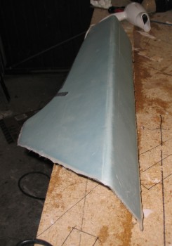
While the CS109 bracket layup cured I returned to the garage to check on my Right rear armrest layup. It looked good & cured enough that I could remove the duct tape. I did, however, leave the peel ply on (I learned that lesson of removing peel ply too soon on my NG30!).
[Also, remember I peel plied the entire surface because per plans it simply gets installed into the fuselage with 2 plies of BID overlapping about 1 inch onto the fuselage sidewall. However, since I’m not mounting these right now & don’t want them to get tore up in the move, I’m glassing only 1 ply now, and then later I’ll add a corner BID tape & another full ply of BID when I do a final glass of the armrests into place.]
I then went back to check on my CS109 bracket. I checked the layup and it was nearly completely cured (I used fast hardener) so I razor trimmed the bracket & fuselage side wall.
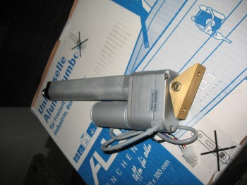
Here’s a shot of my pitch trim actuator with it’s new & improved larger Alodined bracket attached.