
I started off today acting upon some information that I got from my buddy Dave Berenholtz down in OZ. He said that his Long-EZ was built in 1987 and that over the years the requisite plan’s holes in the bottom of the Instrument Panel –with the foam exposed to air, etc.– have deteriorated significantly from the edge of the foam not being treated. This jived with what my Instructor from the EAA Composites Workshop stated when he said that builders should always cover exposed foam with either micro or flox.
So today, before I got started on re-installing the CS109 & CS118 control mounts, I decided I would get the lion’s share of this task knocked out. I figured that if I channeled the foam in the lower Instrument Panel holes before I started any glassing, then I would use whatever leftover epoxy I had at each step to use for micro to edge these holes.
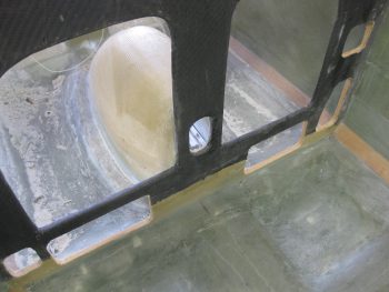
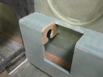
After I used the Dremel tool to remove a small channel of foam around each of the Instrument Panel’s lower holes, I then cleaned up the dead glass from the previous install of CS109.
I then did the same thing in the back seat, and cleaned up the existing glass from the previous CS118 install.
I cut 4 plies of BID on the table (not shown), one for each side of the respective control mounts, and then set about to drill the #12 holes through CS109.
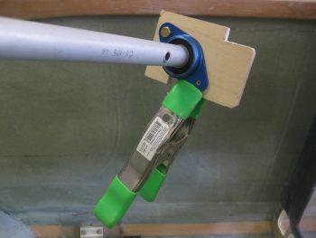
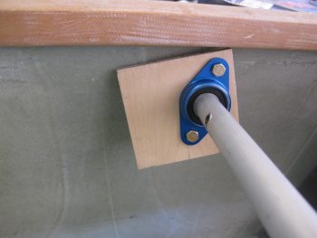
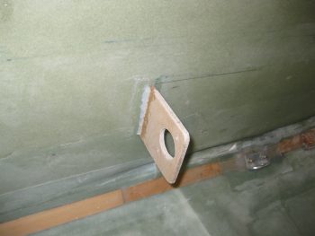
Here’s a shot of the AN3 bolts test fit.
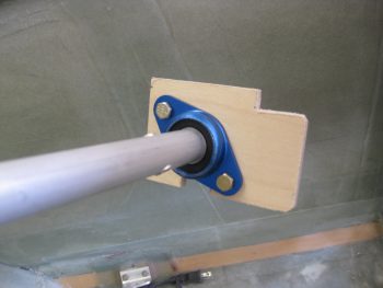
I then did the same thing for the aft-side CS118 and test fitted those AN3 bolts as well.
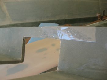
To ensure I could remove the arm rests after the 5 min glue stuck CS109 & CS118 to the fuselage sidewall, I covered the top inside armrests with clear packing tape.
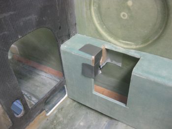
I then 5 min glued CS109 in place to the fuselage sidewall, while taping it in place with duct tape to ensure it aligned properly.
Of course I did the same thing in the back for CS118.
The forward CS109 control mount wasn’t as solidly stuck in place with the 5 min glue, so I went ahead and worked the back CS118 mount first. Below you can see that the 5 min glue did its job and kept CS118 right in place.
I whipped up some MGS285 epoxy with fast hardener, and then some flox, and added flox fillets in the corners.
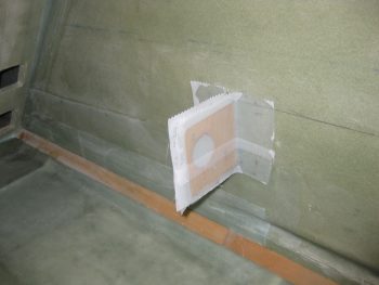
I then laid up 1 ply of BID on each side of CS118 and peel plied the layups.
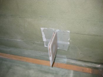
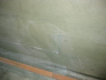
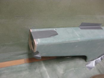
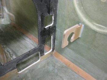
Since I still needed the tape on the front side to secure CS109 in place, I simply laid up 1 ply of BID on each side, but kept each ply small at 2″ x 2″… just enough to lock in the position of the CS109 control mount & keep it aligned properly with the arm rest. I then peel plied the layups [Note the micro in the foam edges of the lower instrument panel holes].
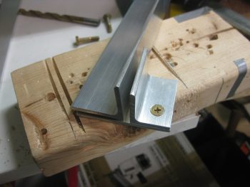
While the CS109 & CS118 layups were curing, I then drilled a #12 hole down into the upper left engine mount extrusion’s bottom reinforcement plate. I then countersunk the hole in the outboard 2024 aluminum angle “L” bracket. I didn’t want to drill the other 2 holes on the other side since I wasn’t sure how much compression there would be when the engine mount was actually bolted in place (the plans say 4 AN3 screws according to a CP… but I seriously don’t know where 4 holes would fit for AN3 screws. There technically is 4 screws/bolts going through the extrusion plates into the lower reinforcement plate, IF you count the 1/4″ bolt that holds on the engine mount tube).
I did realize after I Alodined these parts (below) that I had a major brain SNAFU and should have at least drilled & countersunk the screws on the top (long) extrusion. I could then have simply drilled the holes into the lower reinforcement plate later, since it connects both sides… oh, well. No huge deal, just definitely not optimized as for as Alodine coverage.
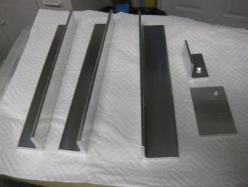
Now, my main Alodine goal for today was to at least get the Engine Mount Extrusions Alodined. I cleaned all the parts with a quick wipe down of Acetone. Then I cleaned them with a 3M pad and Simple Green, and rinsed them thoroughly. I then took them outside and Alodined them. In addition, I was also actually able to prep & Alodine the Aluminum parts for the wing bolt brackets that will allow me to mount the wing bolts in the spar quasi-permanently facing aft to greatly simplify wing mounting/removal.
After I was done Alodining all the aluminum parts & letting them dry, I pulled the peel ply off the CS118 layups & razor cut the BID glass.
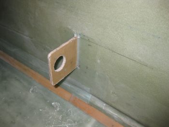
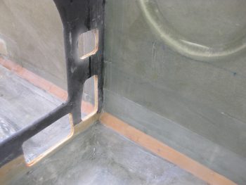
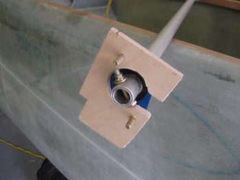
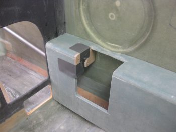
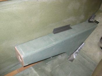
Here’s a shot of the new & improved CS118 glassed into place. Tomorrow I’ll finish sanding the edges & redrilling the bolt holes.
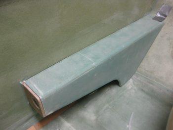
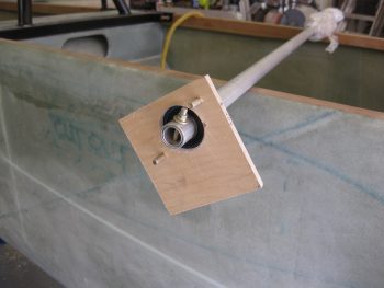
The CS109 mount initial attachment layup came out fine as well. I didn’t realize that I had floxed in such robust fillets, so that sucker will definitely be strong! Tomorrow I’ll add another full ply of BID to the front and aft side.
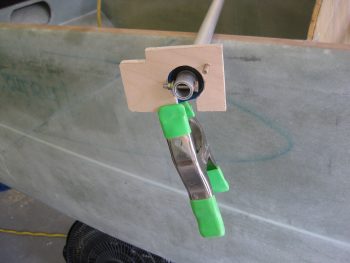
I quickly double-checked the fit & alignment with the front right arm rest, and it fit great!
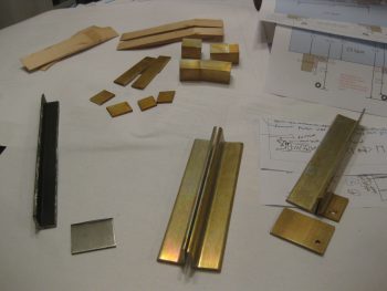
Here’s the last shot of the evening (not, however, the last action of the evening since my hose sprung multiple leaks as I was Alodining this stuff, and my shop still needs some TLC to get some water out from underneath some stuff!!!)
You can see below that the 3 aluminum engine mounts and the outboard spar wing bolt brackets are Alodined. Clearly I still need to finalize cleaning up the edges of the 4130 steel engine mount.
Now that I have a good bit of these of smaller tasks out of the way, I really do plan on attempting to reorg the shop tomorrow in order to get it prepped for finalizing the canard & elevators install!