
This morning I spent a couple of hours planning and diagramming out my oil heat system. I’ve been collaborating with Dave B. on it, but still need to query Nick Ugolini on some of the specifics of the oil heat system he developed.
Next up was simply mounting some stuff. I had some errands to run today, and then dinner with friends tonight, so before I headed out I wanted to get some stuff mounted to ensure my efforts in installing brackets & mounting pads were successful.
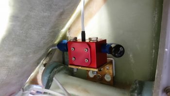
First up was the FT-60 “Red Cube” fuel flow sensor. I used a couple of thick washers on the AN4-17A bolts and put it in place. The spacing was tight, but I got the bolts in nice and snug with the unit correctly aligned with the fuel line coming aft from the fuel boost pump. Thus, the fuel flow sensor install is marked off the list as complete!
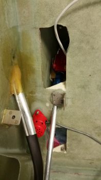
I also double checked the clickbond spacing for mounting the fuel vapor sensor element, and they were spot on. In the pic below you can also see the new GIB right armrest mounting tab just above the engine fuel feed line. Lastly, you can see the mounted fuel flow sensor peaking out from behind the back seat.
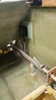
For the Roll Trim servo mounting I carefully drilled out the glass covering the 4 corner #6 screw nutplates. I then pulled out the plastic wrap that I had stuffed into each nutplate to protect it from epoxy. Once all the mounting holes were clear, I then mounted the RAC Roll Trim servo in place. After a slight adjustment upwards of the spring assembly, I then set it in place and loosely attached the 2 hose clamps that when eventually installed for good will allow the servo assembly to rotate the control tube (spring arm up or down), which translates into aileron left or right movement for trim.
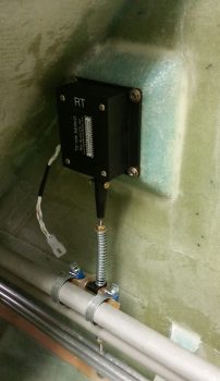
Here’s a closer shot of the mounted roll trim assembly.
I also spent well over an hour mocking up the fuel sump tanks’ access ports, determining both size and shape and testing them out. I finalized an oval shape with an access hole of 2.5″ high x 4″ wide. These access ports will allow me to initially install the Holley Hydramats when need be, inspect them during annual condition inspections or whenever necessary, and swap out the mats in 5-10 years as required. I also determined the width of each interior 0.040″ thick mounting ring to be 5/8″ (0.625″). These are the rings to which the covered nutplates will get attached.
I then made up templates of the fuel sump access port mounting rings and covers in PowerPoint and printed them out. After some judicious sanding on the sump top, I then measured out the access port locations and marked up the sump top.
Tomorrow I plan on making the fuel sump top my sole project to get the sump access ports cut out & locations shaped. I then plan on getting at least the inside of the fuel sump top glassed with 1 ply of BID.