
Well, I have to admit that when I started off this morning by using 5-min glue to mount the fuel vapor sensor module’s clickbonds in place, I realized I have may have been a bit too thick with the praise for MGS over E-Z Poxy when it comes to mounting clickbonds, since I do quite often use 5-min glue to initially hold them in place. However, I will still state that I have not had an issue with either 5-min glue or MGS when it comes to clickbonds.
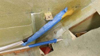
Moving on. I prepped the bottom of the fuel vapor sensor module with clear packing tape, then put some dabs of 5-min glue on each prepped clickbond and set it in place.
A bit later I laid up 2 plies of BID over these clickbonds and then peel plied the layup.
Today I also finished drilling & countersinking the rivet holes for the nutplates that will eventually get mounted onto the armrest (etc.) mounting brackets.
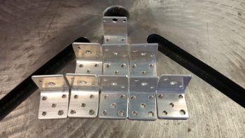
Here’s a shot of the drilled and countersunk rivet holes in the mounting brackets.
I then Alodined the armrest mounting brackets and the FT-60 Red Cube fuel flow sensor mounting bracket.
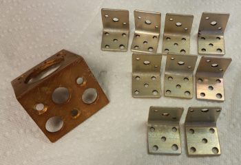
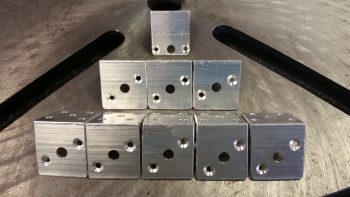
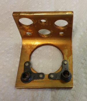
I then riveted the 90 deg. corner -4 nutplates in place on the FT-60 Red Cube fuel flow sensor mounting bracket.
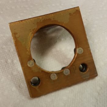
Here’s a shot of the bottom side of the bracket (my Alodine is a bit old, and unlike a fine wine it doesn’t get better with age… maybe that explains some of the splotchiness on my bracket… not sure…)
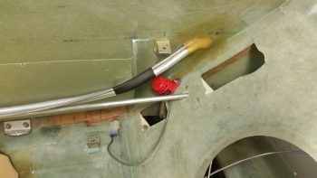
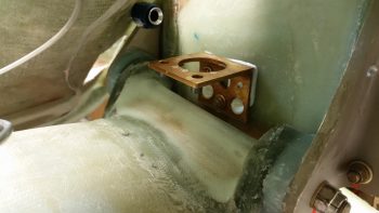
And here is the FT-60 Red Cube fuel flow sensor mounting bracket after I floxed ‘er up and bolted ‘er in!
I then got to work on the Roll Trim mounting pad. I had ordered K1000-06 nutplates for the 6-32 screws that will be used to mount the RAC servo to the fuselage sidewall. Well, I had a “Doh!” moment when I realized that since the RAC servo has corner mounting holes, I should have ordered 90° corner nutplates. Oh well, since the Roll Servo is fairly light and in normal ops not an overly used device, I made a command decision that one rivet tab would do to hold each nutplate in place on its respective G10 Garolate nutplate base.
[Note: Normally this servo would get mounted straight to the sidewall, but since I had to kick in my control tubes about 3/4″ inboard to allow for the CG controls, I am simply “extending” the fuselage sidewall inboard 3/4″ with this foam base]
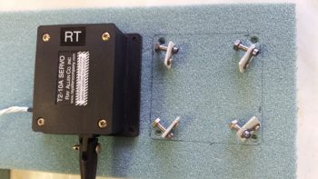
Once I got all the nutplates riveted to their 1/16″ G10 base, I mounted them to the RAC servo and figured out their exact location in the foam. I then notched the foam at each corner and embedded each nutplate assembly.
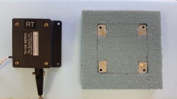
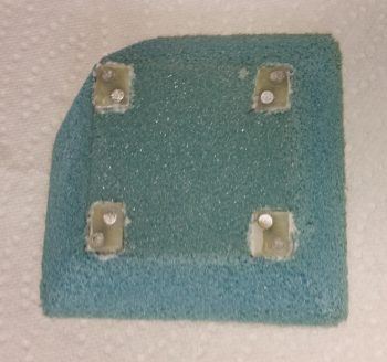
I then taped up the bottom of the RAC servo to use it as a guide, and then mounted the nutplate assemblies back onto the servo. I then micro’d up the bottom of each nutplate assembly and the corner notches in the foam. I set the nutplates (with servo) in place, and once satisfied that they were all in the right position, weighed down the servo to press the nutplates into their respective notched corners (I failed to get a pic prior to this of having shaped the edges of the foam to allow for glass transition to the fuselage sidewall).
Later, after it all cured, I filled each nutplate with plastic/saran wrap to keep the micro out of the nutplate threads.
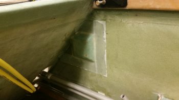
Later still, I prepped the foam roll trim servo base with micro and micro’d it to the right fuselage sidewall just aft of the pilot’s seat. I then laid up 3 plies of BID over the foam base and then peel plied the edges with 2″ peel ply tapes. I double checked the elevation a few times using the RAC servo with the spring push/pull assembly attached. With only a few minor tasks left, like drilling the screw holes and pulling the protective plastic wrap out, I’m calling Chapter 17 – Pitch & Roll Trim Systems, complete!
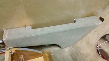
Tonight I floxed in 3 mounting tabs that were screwed to the GIB left armrest. These are 3 of 4 tabs that are located primarily on the aft side of the armrest. I’m planning on building a small framed mounting bracket that will be used to also house the GIB headset jacks and PTT button on the front side of the left armrest, which will have a nutplate attached to it and be the 4th mounting tab.
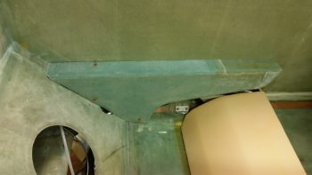
In addition to the left side armrest, I also added another mounting bracket to the GIB right armrest by floxing in place a tab on the aft side of the armrest where it meets up with the seat back.
Tomorrow I really do plan on working on the fuel sump top, but will be going out to eat with some friends so it won’t be a completely full work day.