
I failed to mention that I had a good discussion with both Trent and Brad at E-Mag Air concerning the “A” and “B” ignition timing curves and how that pertained to my specific engine (IOX-340S). They also gave me some very helpful tips on dialing in the timing curves when I start flying this bird.
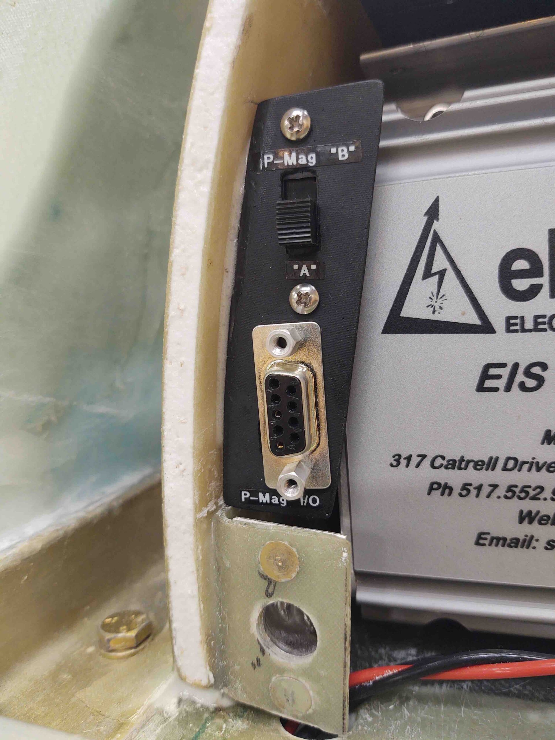
For the switch to fit neatly astride the Electroair Electronic Ignition Controller box, I had to position it with the “A” power curve down. In fact, I had originally wanted to install the switch in a horizontal position so there would be no risk of it vibrating from one position to the other (these are simple slide switches). Well, as serendipity and/or luck would have it, my engine performs best on the non-standard “A” curve so the position was optimized for fitting into the D-Deck.
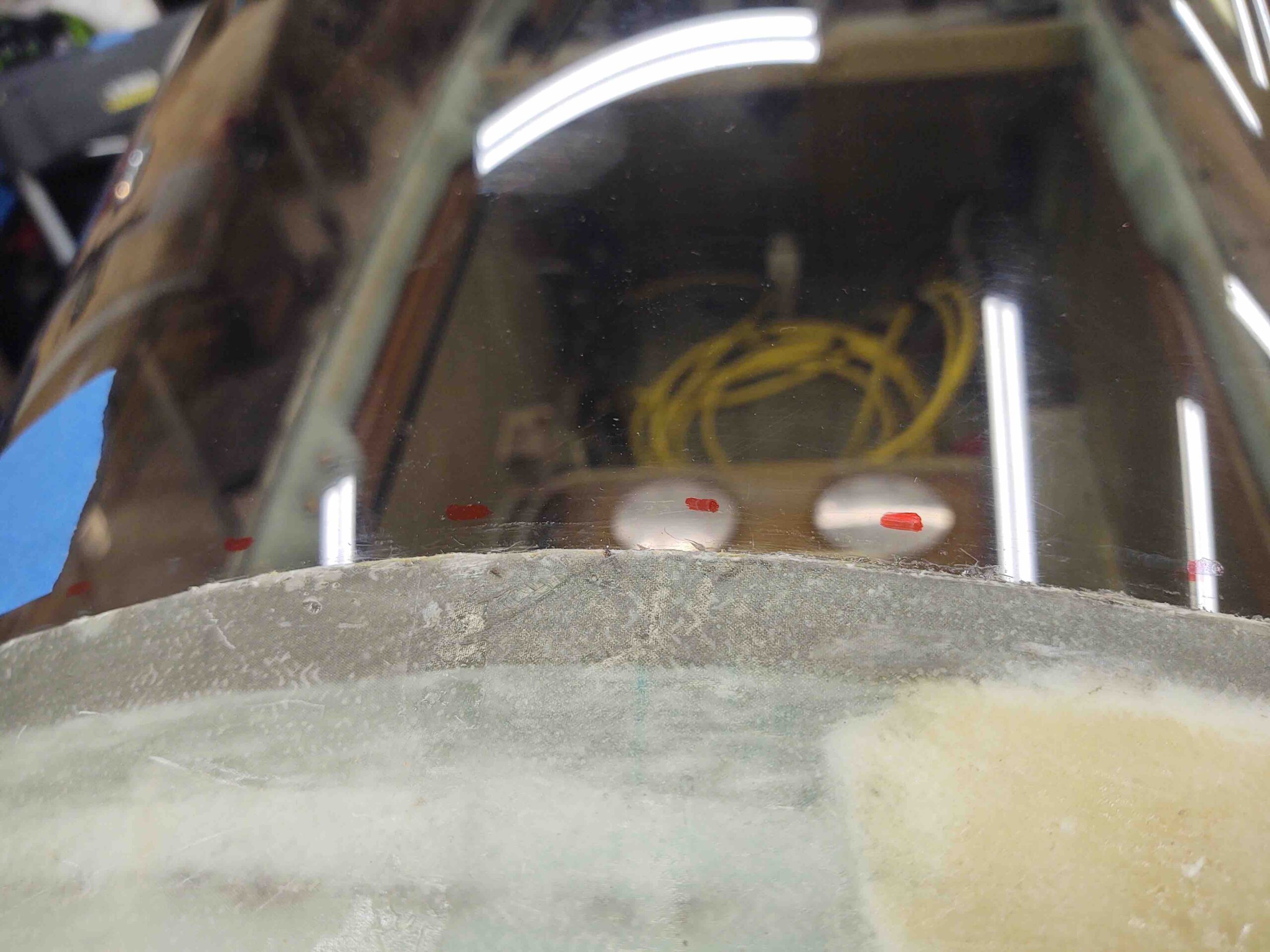
The normal A-B position of a “normal” switch was not captured though, with “A” probably and naturally being at the top position. Not wanting future Wade to screw this up, I figured it prudent to spend 5 minutes labeling the P-Mag ignition timing curve switch and D-Sub connector on this bracket.
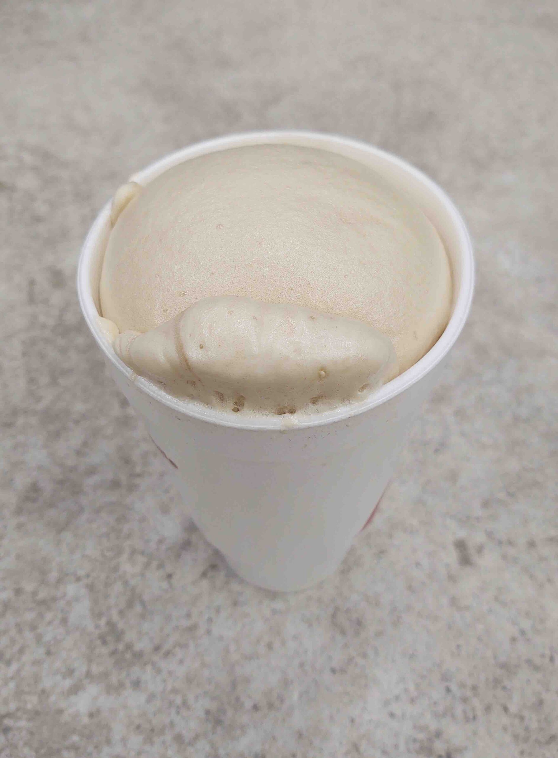
My next task is to deal with the overt angle between the aft canopy and the aft canopy frame, which makes up a good portion of the Turtledeck. I was thinking I might be using pour foam, so I broke mine out after many, many years and did a test batch.
Since I didn’t end up going the foam route initially, with just the right amount in this cup to look like a root beer float I’ll cut it open to check the foam cell structure after I pull a prank on my friend’s 11 year old daughter. Can’t let a good opportunity like this go to waste! <grin>
I figured instead of messing around with pour foam, which for some reason I haven’t become a huge fan of as some builders (probably YET…), I decided for probably an ounce or two more weight I could get a lot more added strength and rigidity filling in the angled trough just aft of the canopy first using Carbon Fiber UNI.
Then after that I might use some pour foam to fill in the area.
So this is Phase I of the aft canopy/Turtledeck reshaping (AKA: angle minimization).
To be clear, this effort is a compromise. My goal is not to lay waste to the aft canopy or the comparably great visibility for the GIB just to get the angle at the back of my canopy to look like every other Long-EZ. I’m not shooting for normalcy in appearance here, I’m shooting for minimizing the angle and smoothing out the transition at this point for better airflow heading into the prop.
That being said, with 2 big protruding humps on the upper cowling covering the engine cylinders, I would say we already have some airflow disturbing draggy things inherent with our pusher design already. So again, to reiterate, I’m willing to give up about 5/16″ of aft canopy… just enough for a good grab of new overlapping fiberglass, to minimize (not eliminate!) this angle. [Note: The angle is really only severe on the top and towards the right side. You’ll note this when you see a lack of new glass on the left side of the Turtledeck].
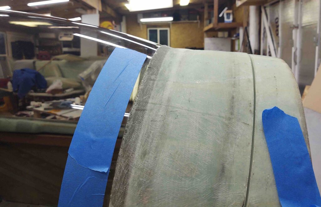
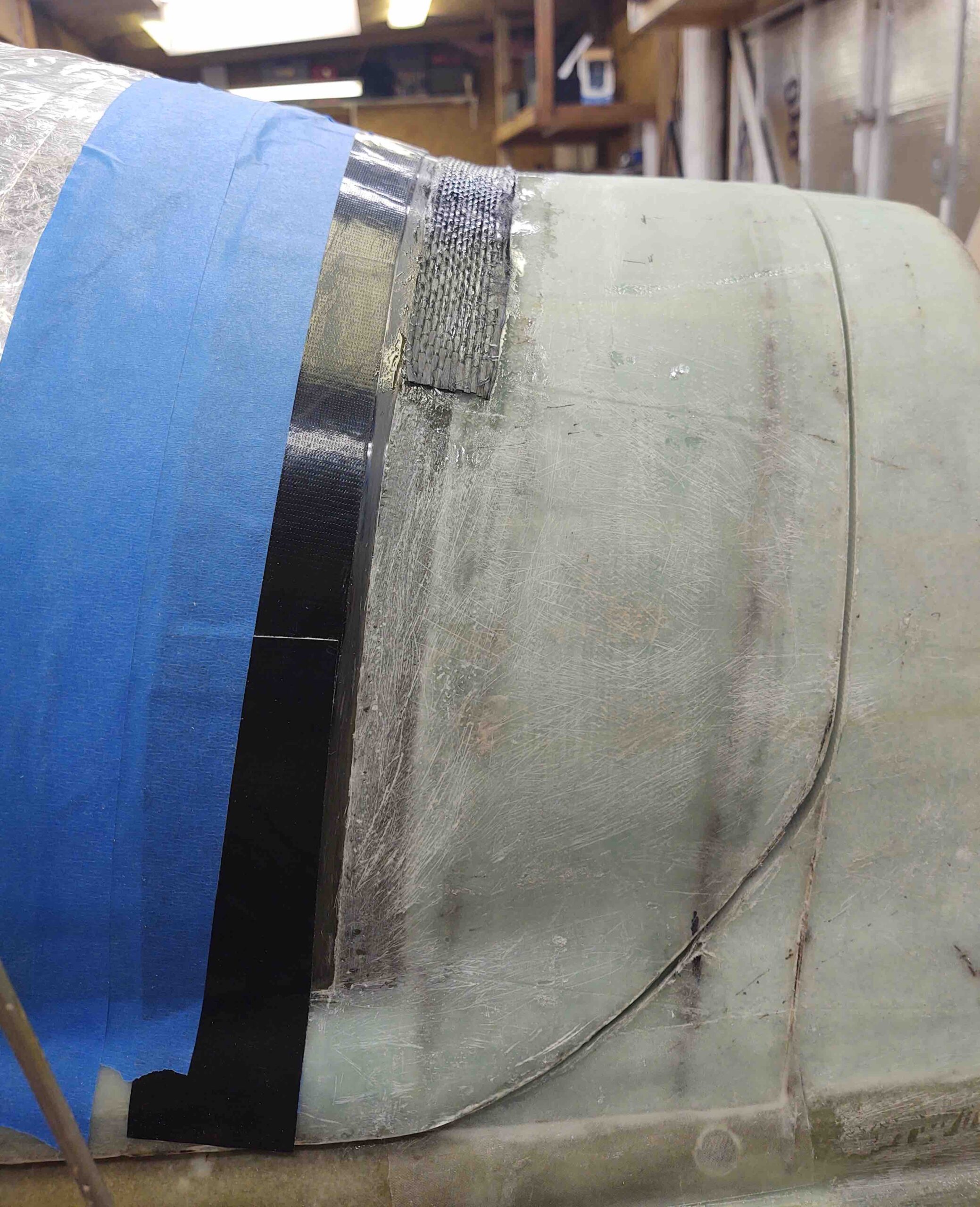
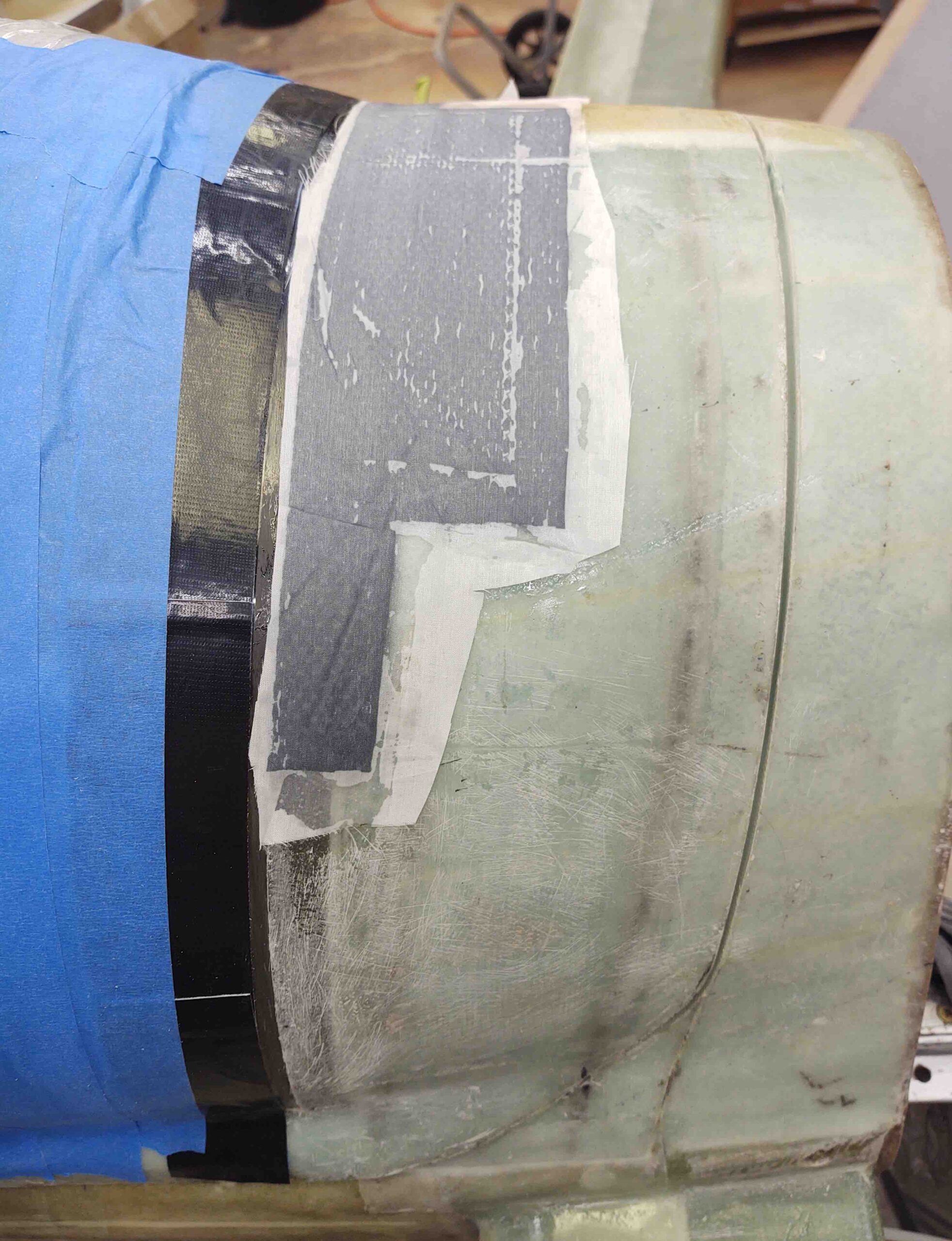
Thus, I started by marking this 5/16″ line with a dry erase marker.
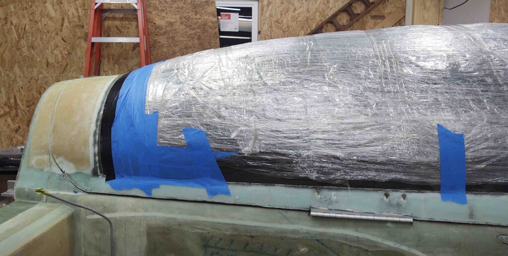
I then taped off the canopy leaving the 5/16″ strip exposed. I also quickly wiped down the canopy and replaced it’s protective covering.
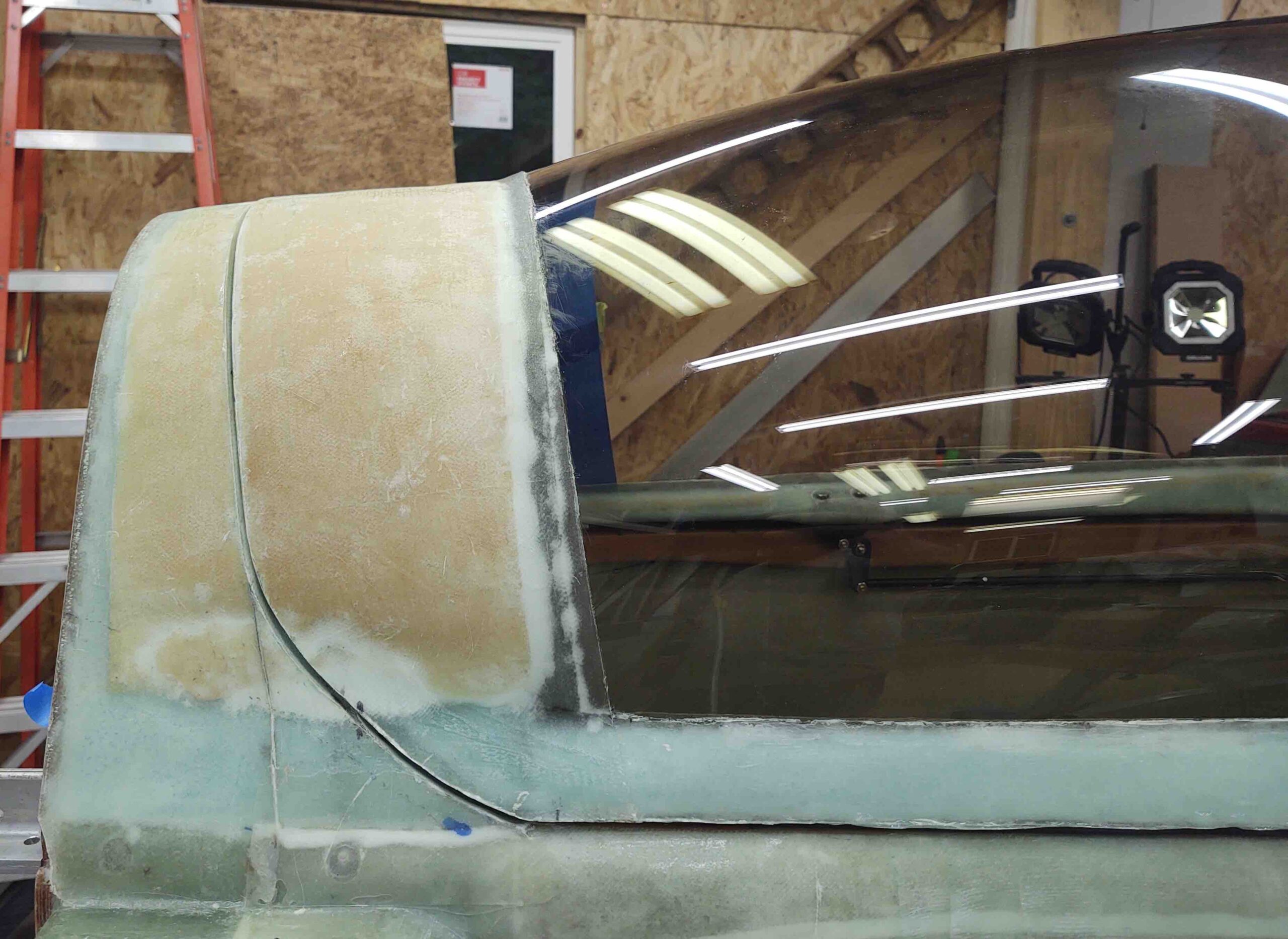
Here you can see the angle I’m talking about, as well as the taped off aft canopy. After taping off the canopy I spent a good 45 minutes sanding both the 5/16″ strip of canopy in prep for glass, and focused on knocking down the edge of glass overlapping onto the canopy for a smooth transition later.
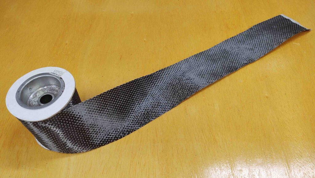
I then grabbed my roll of West 703 3″ wide Carbon Fiber UNI tape.
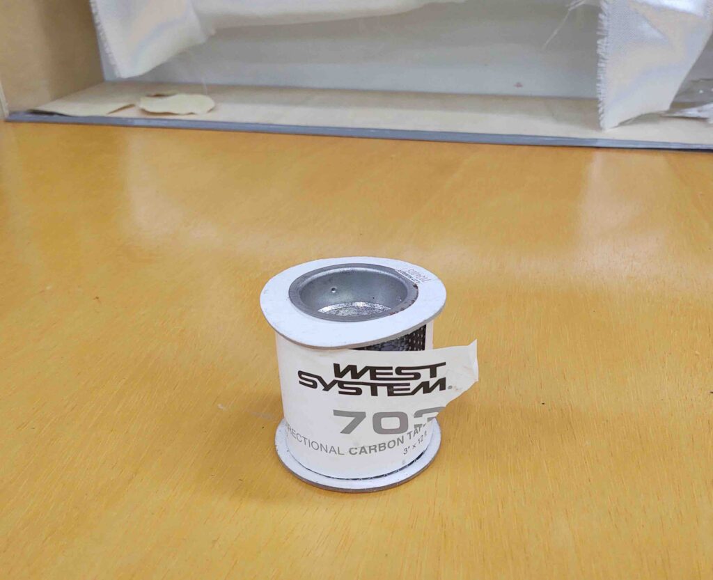
And cut off a 22″ long strip, which is all I used tonight.
I cut about 2/3rds of the CF UNI into 1″ strips. The first 1″ strip was the entire length of the CF piece and I laid it up starting at the right aft canopy corner going up and around. Note that this layup did not overlap onto the any of the canopy at this point, just covering up to the edge of the existing glass.
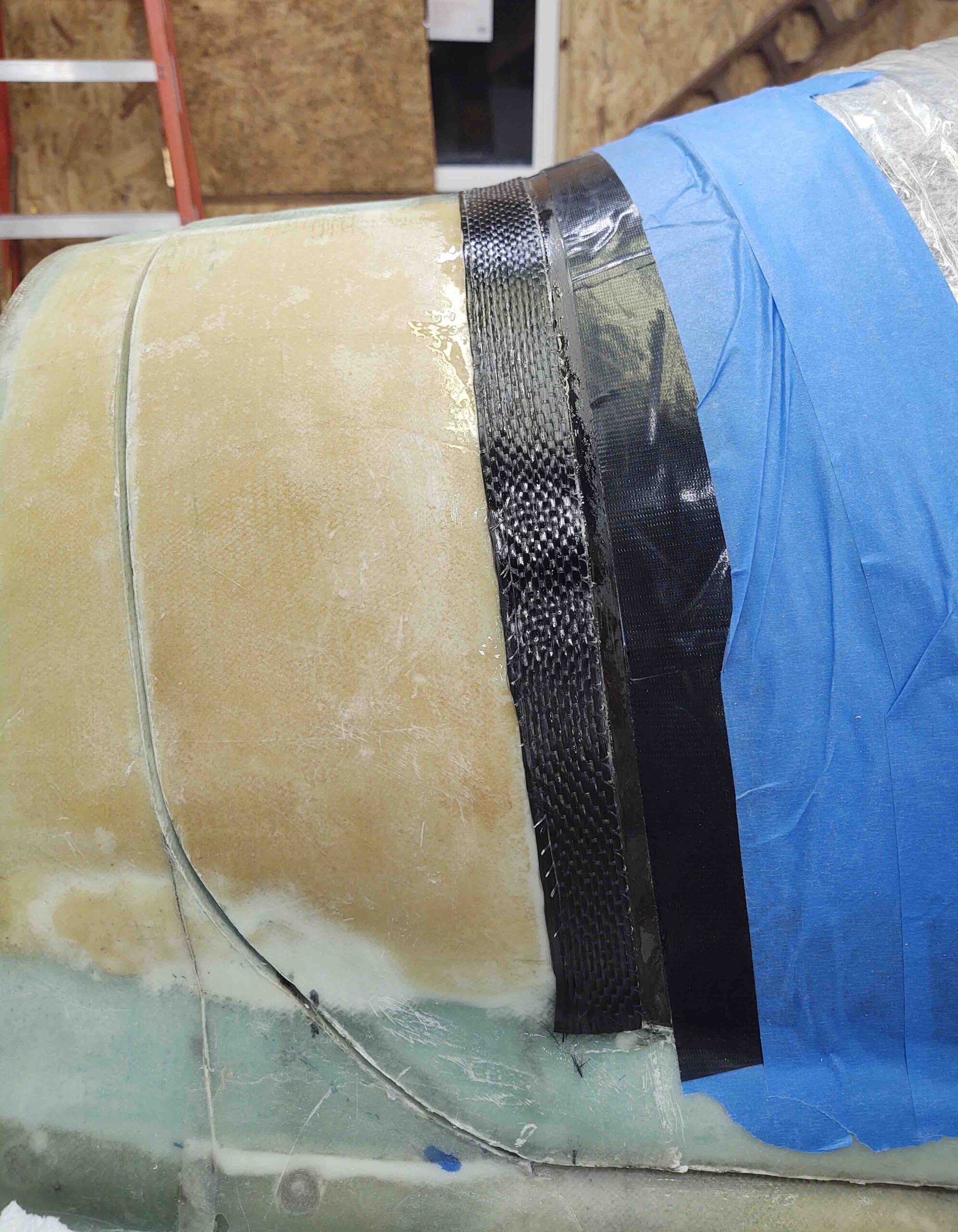
I then laid up a couple more 1″ strips before adding the wider 2″ strips just on top, in stepped fashion.
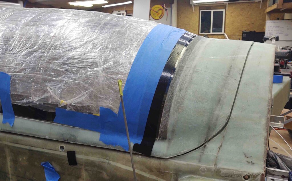
The peel ply I used wasn’t in pristine shape, but it’s good enough for what I’m doing here. Again, this is Phase 1 so I will be adding some BID over top of this. Also, with the distinct notable difference this CF fill has already made to mellowing out the angle, I will do a hard assessment whether or not I’ll use pour foam for such a shallow fill at this point.
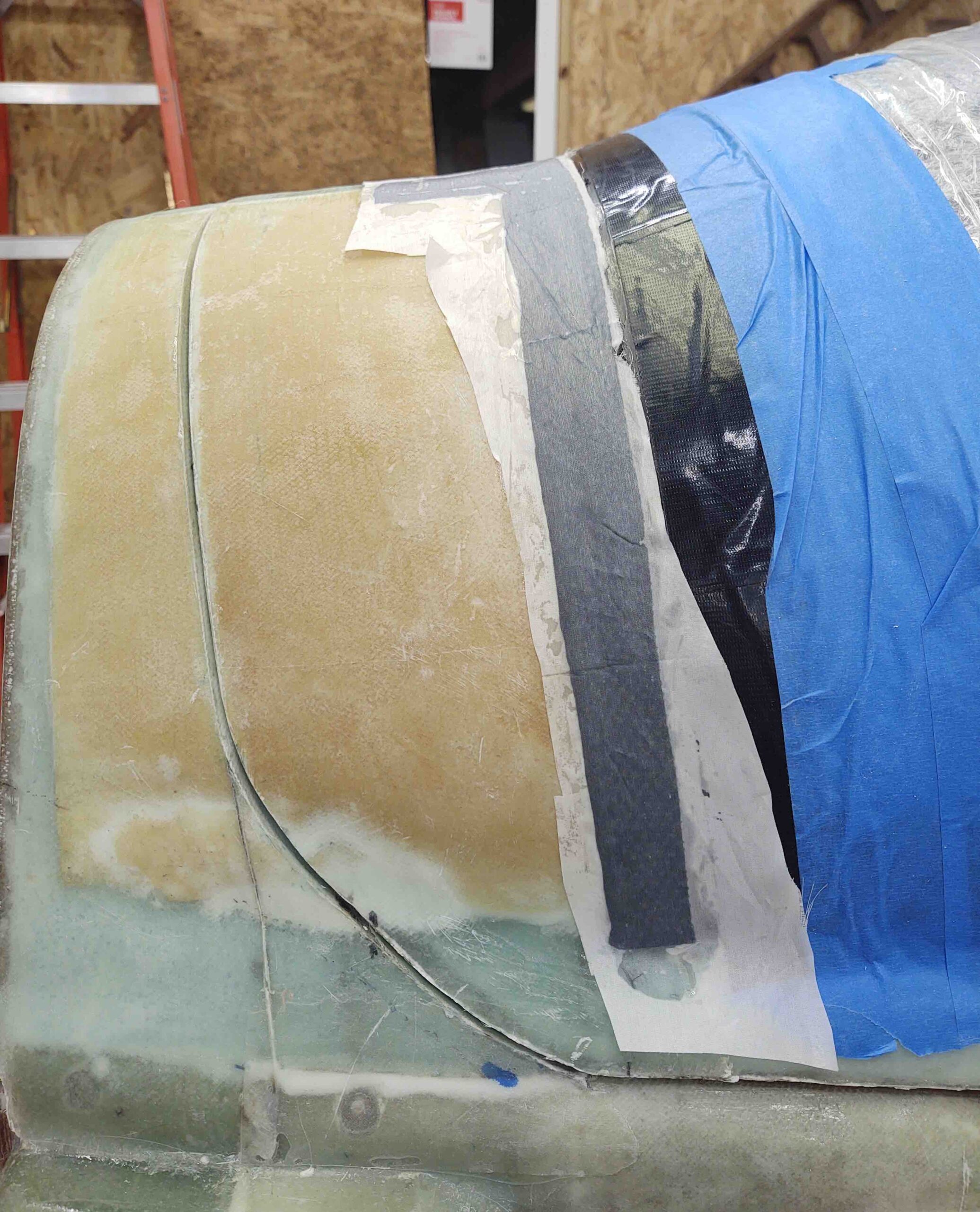
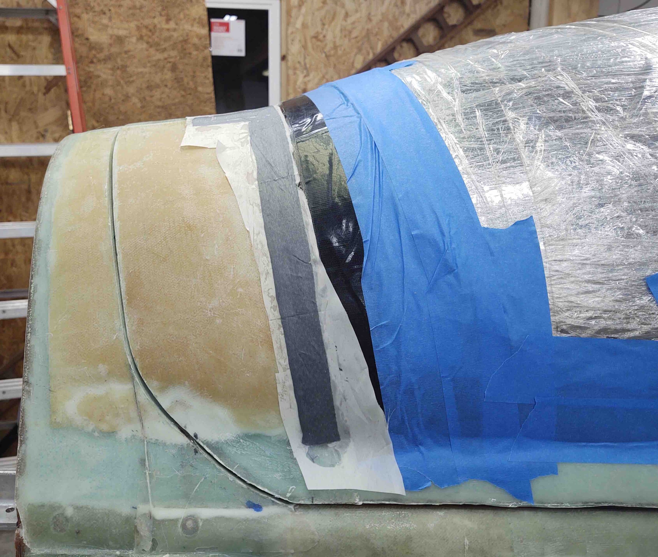
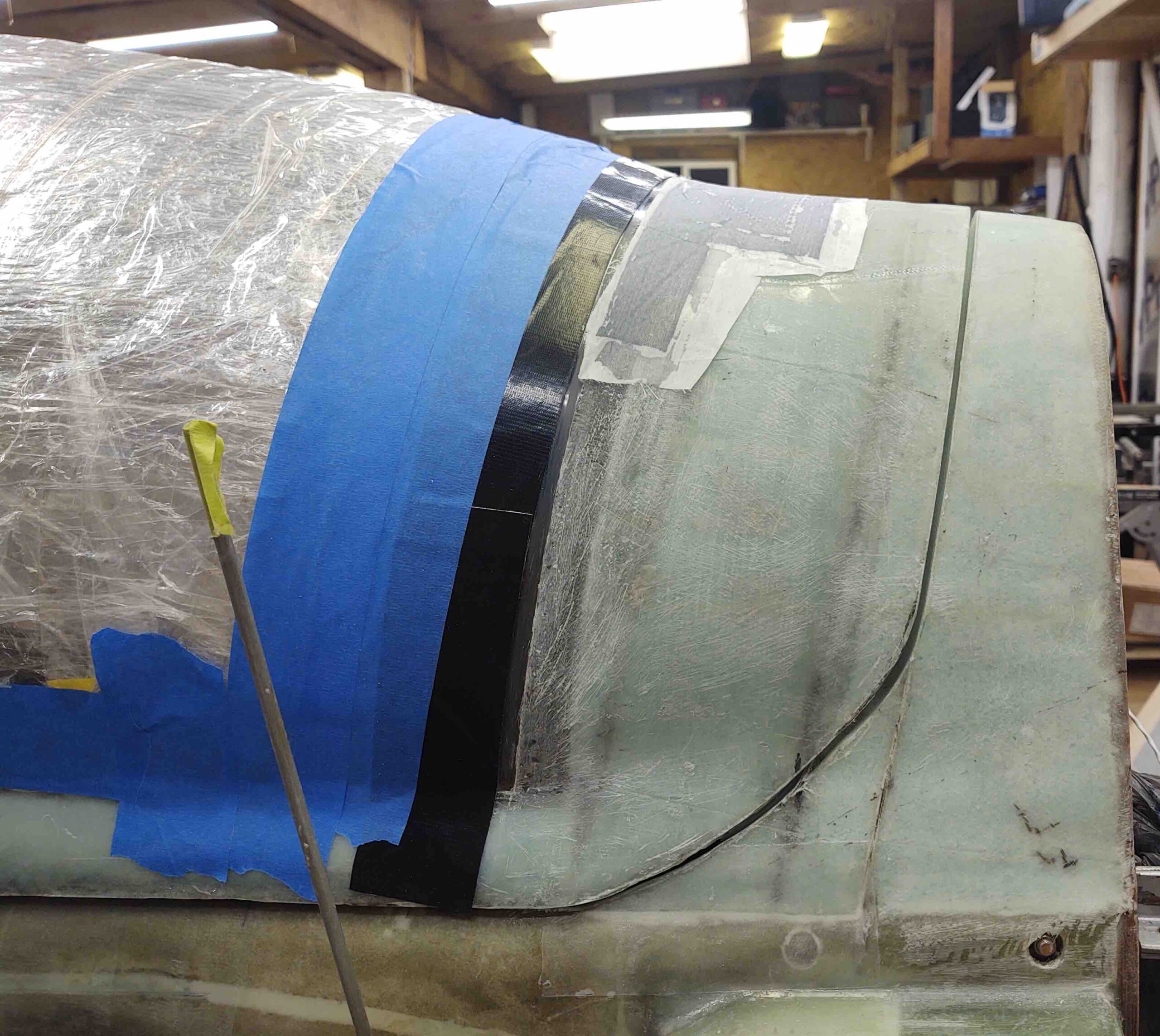
Here’s a couple more shots focusing at the best 90º elevation I could get on each side to assess the angle. I can tell a very notable difference already, and think another ply or two of BID overlapping 5/16″ onto the canopy should really make a huge improvement. Especially later when the finishing micro fill will lessen this angle even more.
With the CF left to cure, my shop tasks were done for the evening. I went back inside the house, made some dinner and assessed the wiring “harness” requirements for my Trig TT22 transponder and Trig TY91 COM2 radio. After my late dinner, I got busy working on both.
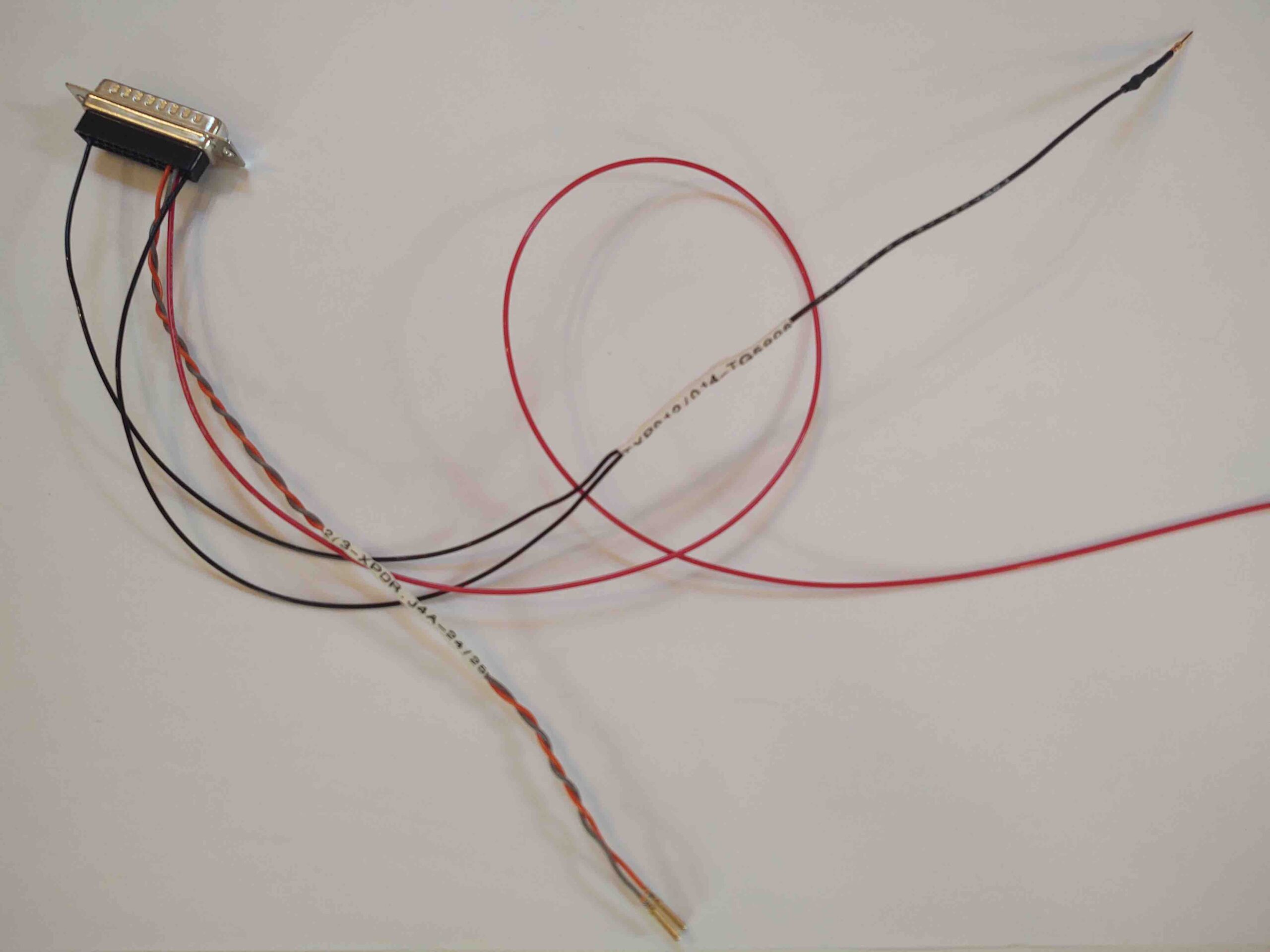
Here is the Trig TT22 wiring harness, with power, ground and HXr EFIS control wires installed. I already have the WAAS GPS feed wire hanging off the Garmin GNS-480 harness, and a throttle handle Ident pushbutton/switch wire with its name on it coming from the P4 CPC (throttle handle) connector. With that, this thing is ready for install.
(Wiring these harnesses highlighted that I was short on wire label heat shrink, so I ordered another couple cartridges…which should be enough to finish off this build).
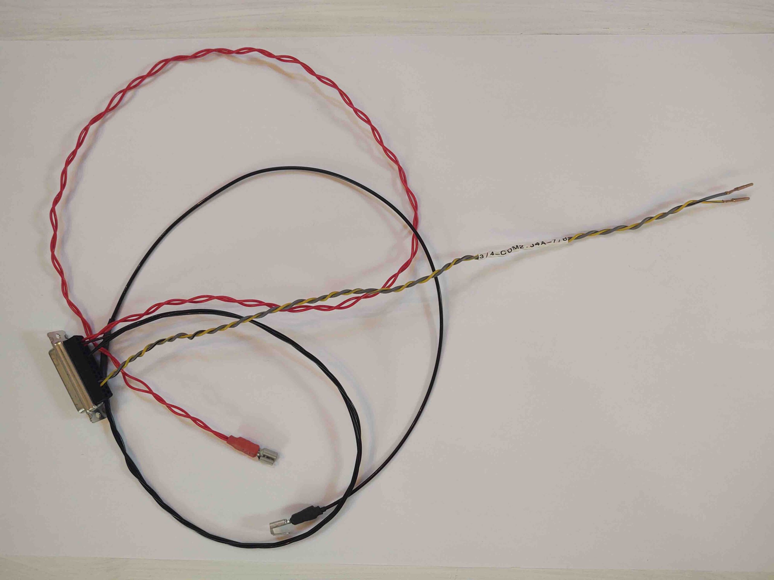
Here we have the beginning of the Trig TY91 COM2 radio wiring harness, also with power, ground and HXr EFIS control wires installed. The remaining few wires that need connected all go to Relay 009 which controls switching COM1 and COM2 radio connections (microphone, PTT, etc.) to the Dynon intercom via the switch on the control stick. Those wires are also completed and installed in the Instrument Panel mockup.
Speaking of the Instrument Panel mockup, I cleared a spot in my office and moved a small Ikea table from my dining room into the office just for it. So the panel mockup is out of the corner and off the floor, ready for reassembly on its own table (pics coming soon!).
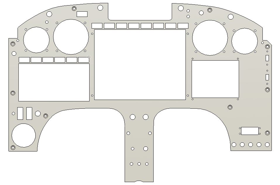
As I was checking over the state of the panel mockup, and doing some impromptu dusting, curiosity got the best of me and I cracked open the panel’s Fusion 360 CAD file. That led to another hour of adding in the latest tweaks to get the panel pretty darn close to its final plasma cutting state. My main focus was reposition the switches on the center strut between the leg holes to then position the mounting holes for the RAM ball mount, the result of my iPad operational positioning testing last week.
Tomorrow I plan to press forward with the aft canopy/turtledeck angle minimization task, and then continue on with more canopy stuff until finished with Chapter 18.