
Today I started out by removing the inline resistor on the right fuel site gage LED power wire. This resistor of course was conveniently located in the right strake baggage compartment.
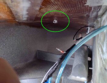
In trying to grab a shot (next pic below) of the wire, I got this shot with the 3-LED baggage light cluster in focus… so you can see those.
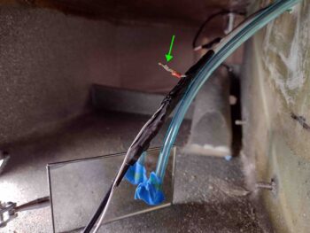
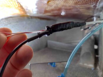
And here’s a shot of the right fuel site gage LED power wire sans resistor. It was just around the corner of my view and a little difficult to work with, thus why it’s not looking overly clean and spiffy.
I then used a crimped on connector —which is a rarely used item for me— since it was much easier and faster to reconnect the power wire than soldering would have been.
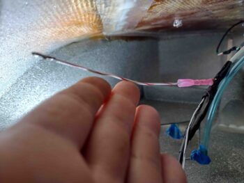
I then hit the connector with the heat gun prior to adding a length of heat shrink and hitting that with the heat gun as well.
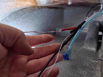
I then wrapped the new connection and other wires in the bundle with electrical tape before securing it with a zip tie.
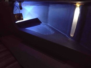
After finishing the wiring for the right fuel site gage and baggage area LEDs, I fired up both sides to compare the lighting of the fuel site gages. The left side, with its new LED light, is clearly brighter. That being said, I assessed that the right side is bright enough to meet the requirement of allowing the camera to view the gage during night ops.
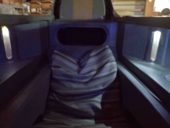
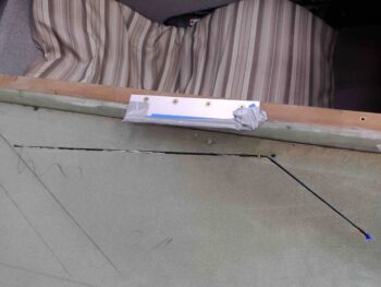
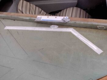
I then grabbed a couple shots of the GIB strake opening showing the lit fuel site gage and baggage area.
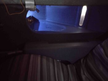
And a shot of the lit right baggage area from the front side pilot’s seat.

After my final test of the right fuel site gage LED and baggage area LED lights, I buried the wiring on the top side of the strake in the foam channels. I’ll note that I did add in a resistor on the top side wire leg going to the 3-LED baggage lights.
I also scuffed up the cured flox/micro in the small holes that secure the GIB map light.
I then micro’d up the channels to bury the wires and also the small holes for the GIB map light. I then peel plied all the micro.
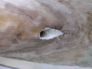
I used the leftover micro from burying the wires on the topside strake wire channels to apply it to the right strake LE root pilot fresh air vent inlet. I’ll clean that up and assess next steps in conjunction with glassing the strake top.
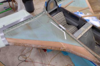
I then sanded the top of the right CS spar and all the areas I missed previously to finalize the prep of the right strake top for glassing. I then taped up the surrounding wing edges to protect them from any errant epoxy or flox/micro contamination.
And with that folks, I called it a night. Tomorrow I’ll be focusing primarily on installing the CS 125 and CS126 aileron control tubes to finish up the firewall aft aileron control installation.