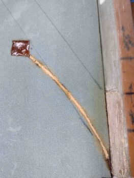
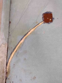
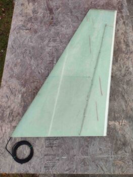
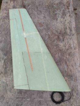
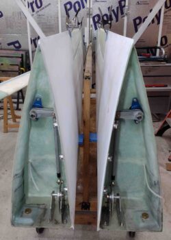
I started out today by whipping up some dry micro using EZ-Poxy and filling in the remaining gaps in the fuel probe wire channels on the tops of the strakes.
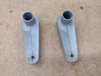
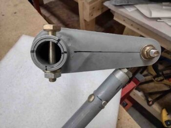
I then grabbed my CS132 weldments and marked the center line on each part.
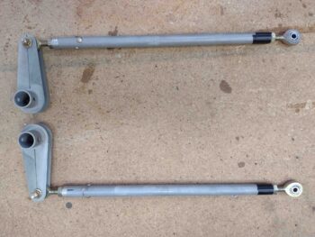
I spent a good little bit of time riveting up one side of the CS129 control tube, for both wings, and then taped the other rod end insert into place since I wanted some wiggle room on determine the final length of the CS129 tubes.
I had to run out and get some errands knocked out, and I returned later in the afternoon. While it was still light out I sanded the left winglet (about an hour) to prep it for install, subsequent glassing and micro finishing. Next up on the sanding docket will be the lower winglets.
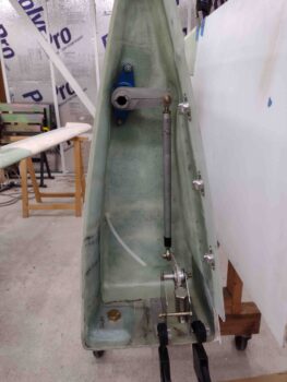
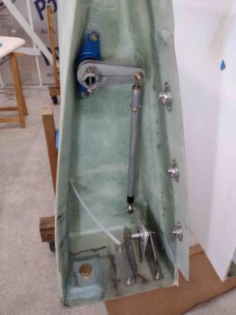
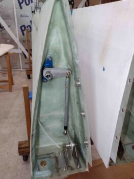
I then got busy installing the wing aileron control system components. As I was working the initial task of determining the 90° angle between the CS132 weldment and CS129 control tube, I set the CS128 bell crank and brackets in place (bottom of pic).
On the recommendation of Wayne Hicks in his write-up, I had also left my CS129 at 9.3″ vs the plans 9.1″ to ensure I had enough length if required.
Well, I could tell that my CS129 was way longer than it needed to be… something didn’t seam right. I did a little looking in the plans and realized that the original rod end inserts did NOT have the 0.2″ tall end caps that the new ones do. So with 0.2″ extra on each end plus my 0.2″ inches for some wiggle room on length, I was sitting at a minimum of 0.6″ too long on the CS129. Even with the rod ends bottomed out I was too long to have any semblance of getting the required 90° between the CS132 & CS129, or the next 90° between CS129 and the CS128 bell crank.
I trimmed my CS129 control tubes down to 8,5″ each and pressed forward. Although the rod ends are still threaded in more than what I would think is “normal,” I could at least dial in the required angles with these components in the wing root.
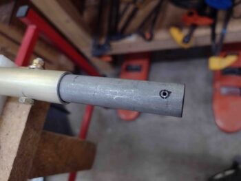
[Note the hash marks on the end of the CS152 tube aligning it to CS132]
Again, although I was focused initially on the 90° angle between CS132 and CS129, I worked the angles as a system to keep the CS129 tube distance off the rib wall consistent and the angle of CS129 with the lower inside wing root surface consistent as well. And before finalizing the CS132 to CS129 right angle, I also made sure the CS129 to CS128 90° angle was fairly close to final.
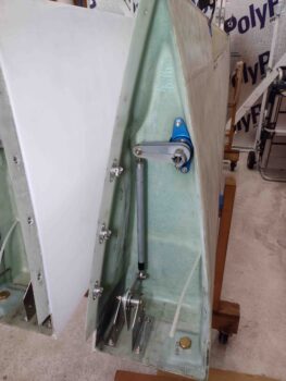
I’ll note that keeping these 90° angles on track resulted in pushing my CS128/CS127 bracket assembly more inboard and further down than I saw in plans or other builders’ installs. I worked it for a good bit to make sure I wasn’t screwing anything up, but given the components I had on hand while maintaining those two 90° angles drove the placement of CS127 brackets to where they are in these pics.
After ascertaining the right wing’s CS132 right angle with the CS129 control tube, I removed the aileron assembly and then subsequently removed the CS151/CS152 combo off the aileron. I hand drilled the top marked bolt hole into CS152 that would be used to attach CS132 to it.
The hole through CS132 was not straight, and being offset a hair required me to hand drill the holes on each side separately… and when I say “hand drill” I mean without the use of my tube alignment block that I normally tape and clamp to a tube to get a near-perfect straight and centered hole.
Here we have the right wing CS132 bolted to the CS152 tube, thus connecting the CS132/CS129 components to the aileron… another significant segment added to the linkage (yes, here my clocking marks are off by about 0.015″ and while not perfect, were a good bit closer when the bolt was fully seated and tightened).
I reattached CS151/CS152 to the aileron and then reinstalled it into the right wing. I then bolted the CS132/CS129 combo to CS152 that enters into the wing root area through the root bearing.
My next task was dialing in the 90° between CS129 and CS128. While doing this, I slowly started securing the CS127 brackets into place by drilling out the bolt holes and securing the CS127 brackets in place as I kept verifying the 90° angles were good. I will note that the third bolt that went in knocked my CS132-to-CS129 right angle off a degree or two, but in assessing this setup I just chalked it up as the cost of doing business… I don’t think I’m going to get much closer than that.
Now, I’ve blathered on about focusing on my two plans-required 90° angles inside the wing root… and as any military planner knows all plans may be perfect up until first contact with the enemy. A primary goal in this setup is to have 20° up-travel on the aileron that is noticeably ensured when the CS128 bell crank hits a hard stop bolt across the CS127 brackets. I was getting that until I secured my last couple of mounting bolts on the CS127 brackets —even though they were clamped tightly in place while I set the component configurations.
It took me a good 45 minutes of slowly dialing in the rod end in/out threaded length and thus negating my oh-so-conscientious focus of nailing the CS129/CS128 90° angle.
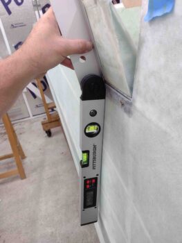
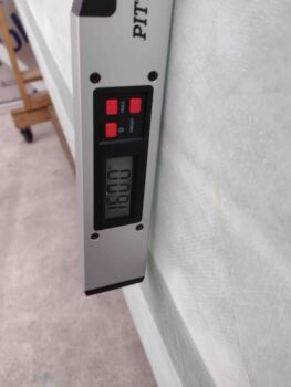
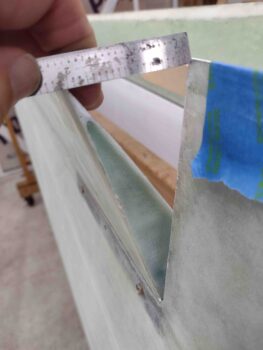
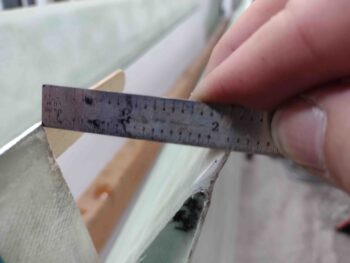
To get my 20° aileron up travel (above… 180-160 = 20) —which equates to a hair over 2″ swing/gap between aileron trailing edge vs wing trailing edge— I had to come off my CS129/CS128 90° angle by an estimated 2-3°. Again, the cost of doing business IMO. If anybody out there has any insights or a better technique, please let me know.
I then repeated the whole affair on the left wing. Being better mentally prepared and knowing how to initially set everything up fairly close to my final configurations not surprisingly made this exercise go much quicker and smoother on the left wing.
After all the aileron control components were installed on the left wing, and with again needing to sacrifice a degree or two off my near perfect CS129/CS128 90° angle, I was seeing almost 21° on my aileron up-travel and 2.1″ gap between aileron and wing trailing edges.
I’ll note that the last half inch up travel on my left aileron is marked with the inside bolt squishing into the interior wing foam… so I still have a bit of house cleaning on the inside of that channel to accomplish.
Early next week I’ll receive, mount and dial-in the MM-4 rod ends at the CS129/CS128 connections, where the black electrical tape is currently and temporarily securing the rod end adapters in the pics below.
It was quite late, but excellent progress on the day. Although I do have a couple minor tasks to complete, I can finally say that I’ve finished Chapter 19!
As par usual, I headed in for a late dinner and to check over my notes.

