
Today was a good day in regards to the rudder installs… not so good for the engine components configuration.
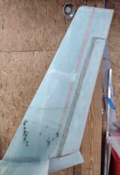
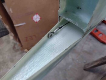
First, here is a shot of the right winglet’s Internal Bellhorn arm pivot channel. Yes, there is some blue foam peaking out from under the micro… a future project to jam a ply of BID up there. Not a high priority nor does it make it un-airworthy. Pressing forward.
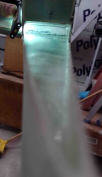
My plan starting off is to have the right wing root rudder cable situated as far outboard as possible…
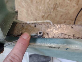
with 6.25″ of cable from the aft corner of the rudder conduit opening of the wing exiting out of the Internal Bellhorn channel.
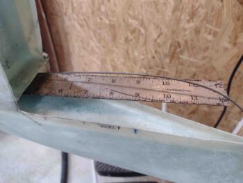
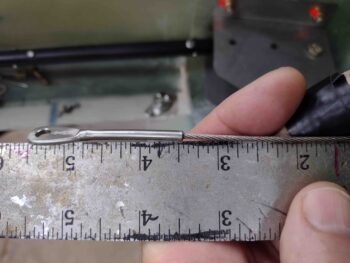
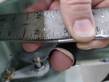
I then swaged a thinned AN111-C3 onto the right rudder cable at this 6.25″ mark. I’ll note that unlike my test swage on the left side, I left the cable long to allow me to pull it tight around the AN111-C3 bushing. This worked infinitely better than pre-cutting the cable.

My final length showing out the wing end was 6-3/8″… however, the wing root rudder cable connector actually slid into the conduit a little bit (see below bit).
I trimmed off the excess cable and then put a piece of heat shrink over the trimmed cable.
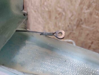
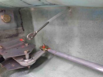
And attached the Internal Rudder Bellhorn to the right rudder cable. Note that I have plenty of rudder cable accessible to easily attach the Bellhorn arm.
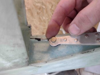
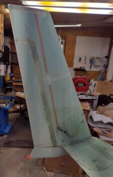
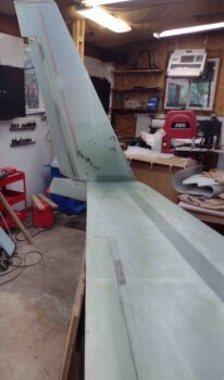
Here we have the right rudder installed with the Internal Bellhorn attached to the rudder cable. In pic #2 the rudder is kicked out full swing by pulling the rudder cable at the wing root. Success!
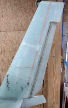
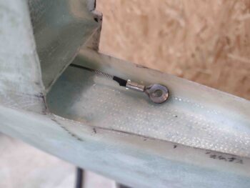
With the right rudder at neutral, the exposed rudder cable exiting the wing root rudder cable conduit is just under my planned 3.5″.
I then repeated the same process on the left rudder.
Here the left rudder AN111-C3 bushing is swaged to the left rudder cable.
Here we have the AN111-C3 bushing swaged and heat shrunk to the left rudder cable.
I then installed the left rudder and tested the rudder pivot outboard by pulling the cable inside the wing root. Success again with the rudder pivoting out full swing by only manipulating the rudder cable.
Now, although I targeted 6.25″ of cable length exiting the left winglet’s Internal Bellhorn arm channel, for some reason with the rudder at neutral the amount of rudder cable exiting the conduit is 2-5/8″. Not really an issue since I have plenty of cable to allow me to easily mount the rudder… just a bit odd that it ended up like this.
Ok, rudders are good… some minor tweaks required of course as par usual. No biggie.
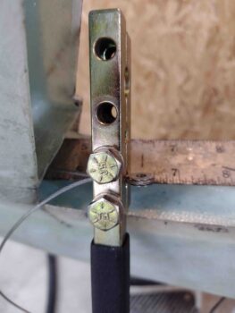
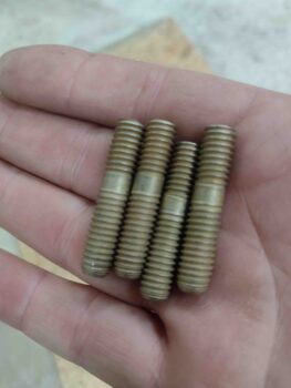
But boy did I hit a number of brick walls as I started work back on the engine. First off, the studs on the cold air plenum are simply too long to work. Technically I could add spacers to the 2 top studs and make them usable… but the bottom 2 studs won’t even allow me to get a nut on there to secure the air induction 90° elbow.
I had planned for this, so quite some time ago I ordered shorter studs from ACS. However, these longer studs are simply FROZEN into the cold air plenum and are not coming out (yet!). I tried the double nut method, thread penetrator, heat, all the above… nothing worked. I talked to the local auto parts store and even my Long-EZ building buddy Chris Seats. I finally ended up ordering a somewhat expensive stud remover tool off of Amazon as a last resort.
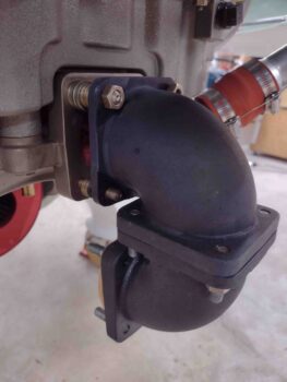
With the long studs still in place, I pressed forward with installing the required air U-turn elbows for my configuration, which you can see below: Filtered or RAM air enters system via RAM air can which will be connected to the fuel injection servo with a short length of SCEET tubing. Then air exits fuel injection servo and enters elbows for U-turn into the cold air plenum, which then distributes air to the individual cylinders.
Even though the long studs were in place, I could press forward with the interim install to allow me to put the bottom cowling on to facilitate the top cowling install. Right?! Wrong!
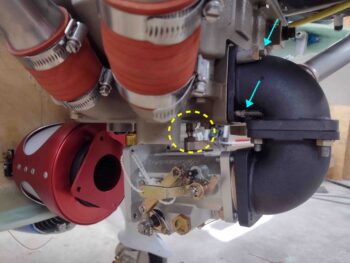
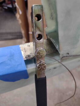
The cowling would not seat properly due to the fuel injection servo sitting about a 1/2″ too low. I do have some wiggle room, but that means swapping out (read: buying) my bottom 85° elbow for either another 90° elbow, or perhaps even a 95° elbow. I’ll do more configuration tests over the next day or two to figure this out. Plus, there are threads showing on the top 90° fuel elbow (yellow circle) which may allow me to thread it in deeper into the servo body. Again, a fair bit more research required here to finalize this specific install. And, again, as per usual…. space is TIGHT.
Time for a drink and some dinner!