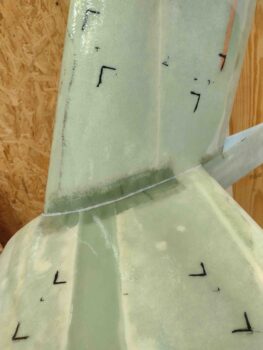
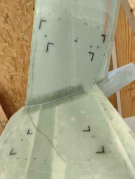
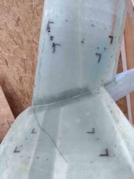
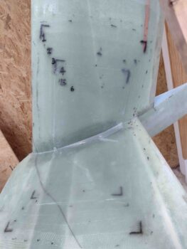
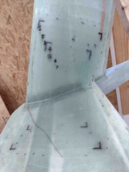
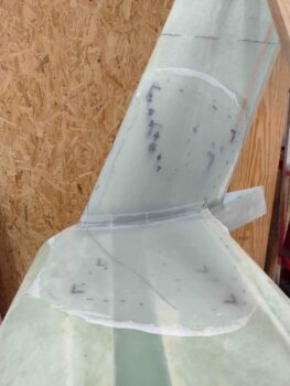
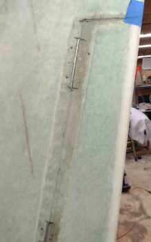
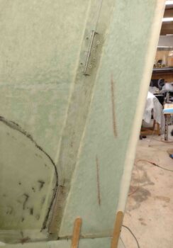
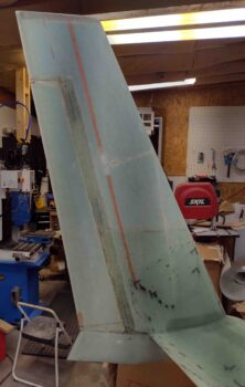
I started the right wing and winglet Layup #4 this morning with a small flox fillet at the inside corner, as I did on the left side. This is to ensure no air bubbles work their way into the corner.
I also slathered up the areas on the wing and winglet that will receive glass with raw epoxy.
Here we have the 2 base plies of BID laid up before the 7 plies of UNI go on.
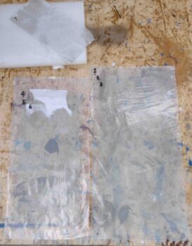
Speaking of UNI, also like the left side, I prepregged the first 3 plies of UNI (1-3) together —on the right below— and plies 4-6 together, which are on the left below. Here I’ve wetted out the first set of UNI and have almost finished wetting out the second set. Ply 7 is on its own, up top.
I then laid up the first set of UNI, plies 1-3.
And then the second set, plies 4-6.
Here the plastic sheeting is still on. I took this shot to show that on Layup #4, versus the outside corner Layup #3, placing the UNI is a bit trickier because of the curve of mainly the winglet, but a bit of the wing too. The center of the layup is fine, but the outside edges in the corner have to be “pushed” further in that then pulls the UNI fibers in towards the corner on each side, while the center fibers are happy from the start. This messes up the original planned, marked spacing a little bit… no big deal, just something to be aware of.
I then pulled the plastic from prepreg setup 2 above, and then added the last ply 7 of UNI to complete Layup #4.
I then peel plied the entire Layup #4 and left it cure.
Now on to rudder installs, but first . . .
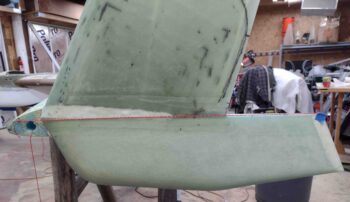
I’m having a slight possible issue with my rudders that I wanted to investigate more fully. The top and bottom “horizontal” edges of my rudders are not exactly parallel to each other, which I’ve confirmed by measuring them (of course I did this early on too, slightly different results!).
With the winglets unmounted it certainly looks as though the top edge and bottom edge are parallel to each other. Then when the winglets were mounted and the top rudder edge was cut horizontal, I assumed that the bottom rudder edge would be horizontal as well.
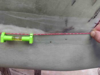
Now, I did trim the bottom edges to match each other and be even with W.L. 18.2. On the right the cut was a bit more at an angle down, so I could see inducing this seemingly nose-down slant on the bottom rudder’s edge. But my cut on the bottom left rudder was virtually a straight trim with no angle… and my unscientific string pulled at W.L. 18.2 again shows a straight LEVEL cut.
Again, I didn’t employ the laser (yet) but going from the corner (to lessen the string length and support the level weight) forward to the wingtip shows virtually level with the longerons close to level.
Hmmm, a mystery? I’m on the fence of “fixing” this or leaving it. My inclination of the mismatching, seemingly un-parallel top and bottom rudder edges is to leave them and evaluate further after I hack up the gaps so that they can pivot freely anyway. Probably more to come on this later.
I then grabbed my Fein saw and did a very close trim of the Layup #7 pocket glass on the right rudder. I didn’t sand it yet as I just wanted to get the really noisy part out of the way earlier in the evening.
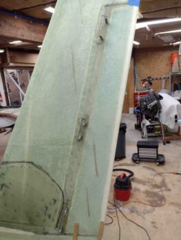
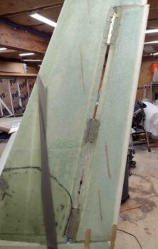
I then pressed forward with the left rudder install. I started by verifying the matching hinge position marks from the rudder to the aft winglet edge. I then cut out the hinge notches on the winglet side to 0.2″ deep.
Here is the rudder back in place after I cut the winglet hinge notches. I’ll note that with the rudder trailing edge even with the winglet TE that my max gap between rudder and winglet is less than 0.02″
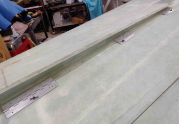
I then verified the alignment of the hinges to each other with a long straight edge. The middle hinge needed to be pivoted upward (outward/forward) on the bottom side literally maybe 0.010″ max. So I started on the bottom and top hinges to get them riveted into place.
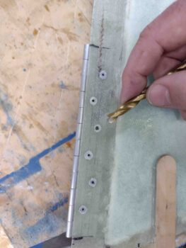
Another minor issue I ran into was the BSC-44 countersunk rivets are 120° countersinks, and I only had the “standard” 82° and 100° countersink bits on hand. I thought for a bit and did a quick check, and sure enough my drill bits on hand have 118° tips… close enough. If 2° in fiberglass and aluminum is going to knock me out of the running, then I have much deeper issues… ha!
I also grabbed this pic to show that I rarely use a drill when making countersinks in fiberglass, phenolic and often even aluminum, but rather do a few iterations by hand and check for acceptable fit/depth.
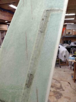
With the hinges riveted in place to the rudder, back on it went AFTER I had marked & drilled 1/16″ holes in the aft winglet edge denoting the winglet side hinge screw positions. The screws are all on 2.4″ spacing for both the 4″ and 6″ hinges (both pics below).
It was now time to add in some nutplates and get this rudder installed. I have to say I’m not sure if I misplaced a bag of K1000-3 nutplates, which wouldn’t shock me. But all I had in my little K1000-3 hardware drawer were 6 nutplates. Ugh! More inventory control problems, caused by that slacker worker… me!
I decided to simply use 1x K1000-3 per hinge for the next 5 days until I get a big batch more in (I dropped an order as soon as I came in the house) or find a bag of them somewhere in this shop (I looked and tend to think I don’t have more on hand). This would allow me to get both rudders installed to a point of being functional in checking travel, edge gap clearances, etc.
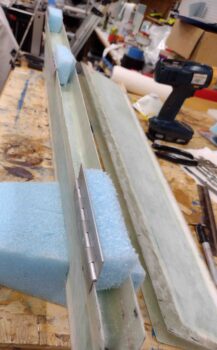
Now I just needed to figure out how to keep the hinges pressed up tight against the inside surface of the winglet to drill the screw holes. I decided to use some scraps of blue wing foam since it’s rigid enough, but I can cram it down in the hinge pocket around and over the protruding pop rivets without any major hassle or harm.
As I put the foam encumbered hinges into the winglet hinge pocket, it seemed to keep the hinges pressed in tightly against the inside winglet pocket surface.
A quick aside on my winglet and rudder hinge pockets. I took Ary Glantz’s advice off his blog and made mine 1.25″ inches deep vs the plans 1″ deep. By the time I sanded down the internal pocket foam I was at minimum of 1.25″ deep, probably more around 1.3″ deep. This eliminates the need to trim down the hinges for them to fit… a hidden little surprise that builders find out about if they keep their pockets at the plans 1″ depth.
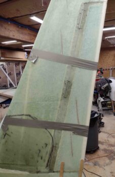
I then duct taped the rudder tight against the winglet to keep the gap between rudder and winglet as tight and minimal as possible.
I then drilled all 1/16″ pilot holes through the hinges and 3 of the holes, one in each hinge, out to 3/16″. Maybe should’ve waited on drilling all the pilot holes… read on.
I then riveted a K1000-3 nutplate to each single (for now) screw hole in the left rudder hinges. I made up a template to keep the angles exactly the same for each nutplate, but the distance to the hinge edge of each hole is just a hair different on each hinge, so the angles are very slightly different… good thing these things are going on the INSIDE of the rudder! <wink>
I then set the rudder back into position on the left winglet. I quickly noted that the top hinges are spot on with the position of the screw-secured hinge.
However, the gap at the bottom hinge means that my screw hole ended up about 0.025″ aft of where it needed to be. The gap is just too wide, and with the screw out and minimal pressure I can push the rudder foward and close that gap up. So the screw hole and nutplate position will need to be tweaked to close this gap back up to where it needs to be… note that the screw is not in the hinge in the pic below: this is the rudder’s natural resting position and gap.
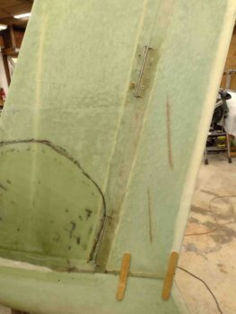
Besides my K1000-3 inventory and the bottom rudder hinge screw SNAFU, I’m really happy with how the left rudder is going in so far. I have no major gaps or misalignments betwixt rudder and winglet, other than those that are self-inflicted.
Clearly I’ll need to work the gap clearances top and bottom to allow free and unhindered rudder travel, but that is all part of the natural progression of the rudder installs (note: the slight rudder/winglet gap below is from the outboard popsicle sticks pushing on the lower winglet and springing the rudder outboard… this is due to me removing the inboard popsicle stick that countered this effect).
Again, it was another very late build outing, so I called it a night and headed into the house to order some K1000-3s! Tomorrow I’ll continue on with my rudder install shenanigans and may start working on getting some of the engine cowling stuff figured out.
