
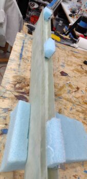
I started out this morning by pulling the peel ply from the right wing/winglet Layup #4. I’m happy to report that the layup looked good. I then spent a little bit razor trimming overhanging glass and cleaning up the peep ply seams.
In addition, since it had been well over 24 hours since I completed Layup #4, I also took a good half hour to carefully remove the 1×2 wood support strut. Now the right winglet is mounted and free standing on its own just as the left winglet. Both winglets are officially mounted!
I then remounted the left bottom rudder hinge with the temp bolt to gage the gap, which I measured at 0.042″ wide… much more than the gap above it and this gap itself that I had measured originally.
I then removed the K1000-3 nutplate, widened the hole towards the aft side (hinge pin) by 0.04″ and then remounted the nutplate. When I remounted the rudder here, I remeasured the gap at 0.017″… a much, much more acceptable gap 0.025″ less than what I had with the nutplate in its previous position.
Left rudder fixed.

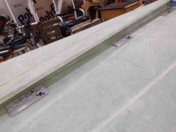
With the left rudder good, I then moved onto the right rudder. I carefully sanded down the forward and top edges of the right rudder where I had added internal rudder pocket glass, and then subsequently trimmed that glass. I sanded down the added glass back to the original line of where I cut out the rudder from the winglet.
Here we have the fine-trimmed/sanded right rudder set back in place inside the right winglet. I’ll note that the seam between the rudder and winglet looked less than a 0.5mm pencil mark.
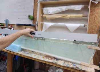
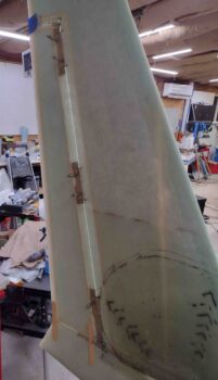
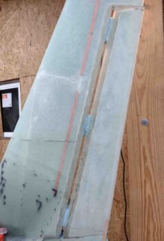
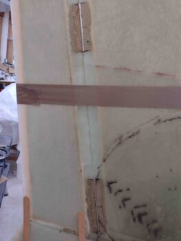
I then set the right rudder hinges in place, ensuring that they were set level and even with each other using a straight aluminum edge. After marking up the rudder hinge rivet locations, I then drilled and clecoed the outboard rivet points on each hinge. Here I’m verifying that the right rudder hinges are aligned with each other.
I then set the right rudder in place with the hinges set in position and transferred the final hinge positions to the winglet.
On the left winglet I cut the rudder hinge notches at 0.2″ deep, which is what is called out for in the plans for the aileron hinges. I’m not exactly sure why, perhaps the sharper angle, but the bottom hinge winglet notch on the left side is simply too wide and resulting gap at the hinge is a bit too big appearance-wise, although operationally there is no impact.
I had planned on cutting out the right wight hinge notches 0.18″ deep, but then settled on 0.185″ deep. Here I’ve cut out the right winglet rudder hinge notches at 0.185″ deep.
Also, to be clear —even though I didn’t grab any shots of this— at each hinge mounting location both on the rudder and the winglet I trimmed the glass so it was angled at 45°, allowing the beveled area of the hinge near the pin to not interfere with the hinge sitting flat in its pocket.
Oddly, just as on the left, the top and middle hinge notches on the right winglet are good, with minimal gaps. However, the bottom hinge again has a gap just a tad wider than what I would prefer. Not a show-stopper, just a preference issue.
I’ll note that once again the gap at the edges between rudder and winglet were nice and tight, looking good as well.
With right rudder hinge spacing and alignment looking good, I then drilled and riveted the rudder hinges in place using the BSC-44 countersink rivets.
Prior to setting the rudder back into place in the winglet, I used the same foam wedges as I did on the left side to secure the hinges flat against the inside winglet hinge pocket for drilling out the screw holes.
However, I noted the issue on the foam wedge for the bottom hinge and realized it wasn’t wide enough just behind the hinge, so I stuffed in a couple stir sticks and piece of cardboard to provide a filler for the unwanted gap.
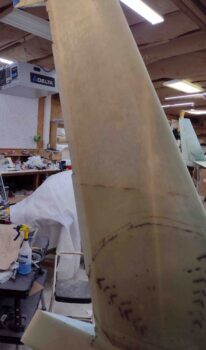
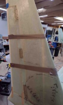
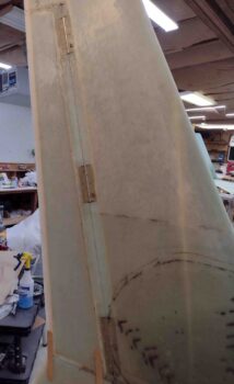
Here we have the right rudder going back into the winglet.
With the right rudder back into the winglet, I verified that its position looked good and gaps were acceptable (again, they are very tight) and then taped the rudder tightly into the winglet rudder pocket.
I then drilled a single 3/16″ hole into bottom screw position for both the top and middle hinge, and at the middle screw position on the bottom hinge (remember that currently I only have 3 K1000-3 nutplates on hand).
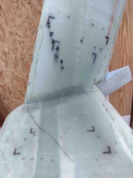
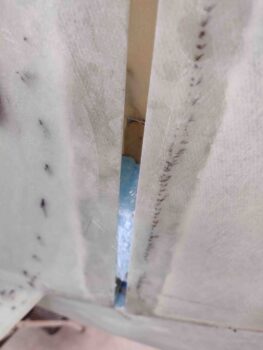
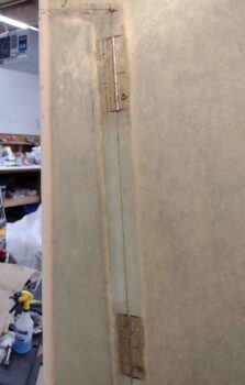
Here are closeup shots of the right rudder hinges drilled screw positions on the winglet side.
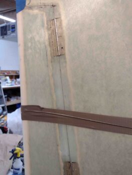
If you look closely, you can see the added stir sticks on the bottom hinge foam wedge to keep the hinge securely pressed up against the inside winglet pocket.
I then riveted my last 3 remaining K1000-3 nutplates on hand to the right rudder hinges.
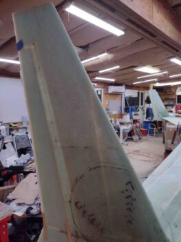
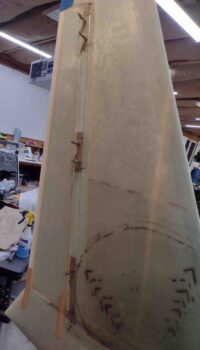
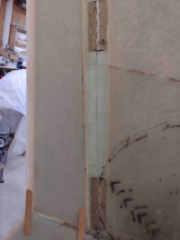
And bolted the right rudder back in place inside the right winglet. Voila! The right rudder is installed!
Again, some closer up shots of the right rudder bolted installed in the winglet. Note the gaps… I’m very pleased with how tight they are.
To be clear, these bolts/screws I’m using here are easy to get in and out so I am using them to temp install the rudders just as I did with the ailerons. After micro finish I’ll will drill countersinks and install the Mike Melvill style flat stainless steel hex-drive countersunk screws to make it all look nice and fancy, with no ugly button head screws hanging in the wind.
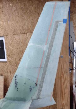
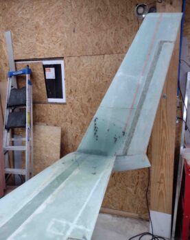
A wide angle view showing both right and left rudders installed back into the winglets.
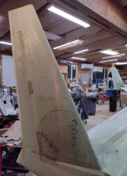
And a shot looking at the inboard side of the right rudder installed into the winglet.
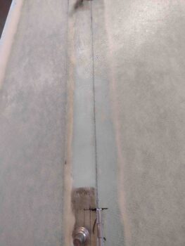
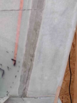
And finally, a closer look at the inboard seam gap of the right rudder and winglet. Looking good!
Tomorrow I’ll be heading over to hang out with some friends for a few hours, but do plan on starting on both rudder pivot clearances and also prepping the engine to mount the lower cowling.