
I started off today by first removing the large stir sticks that were hot-glued in place off the left and right rudders.
I had planned on having to remove the rudders and remount them a number of different times to gain the required gap spacing needed for them to pivot outboard the required 22-26° as per the High Performance Rudder plans.
However, with a little craftiness I discovered that I could sand the edges that I needed to in situ and not remove the rudders at all. Time saved: Excellent!
The 3 main surfaces required to be trimmed in loose sequence are: 1) the bottom inboard edge of the rudder, 2) the top inboard edge of the lower winglet, and 3) the top outboard edge of the lower winglet.
I knew without doubt that with my rudder configuration that I’d be creating a decent gap on the inboard interface between bottom rudder and top lower winglet. In fact, this is the point of initial interference: the sharp forward bottom corner of the rudder hitting the edge of the forward couple inches of the inboard lower winglet edge.
After clearing the inboard edge clearance hurdle, the last and persistent clearance issue until the rudder is at its full pivot arch outboard is between the front half of the bottom inboard rudder edge and the outboard edge of the lower winglet.
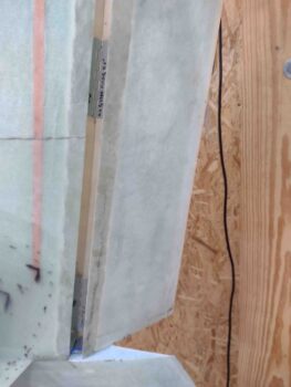
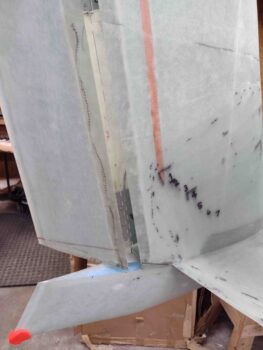
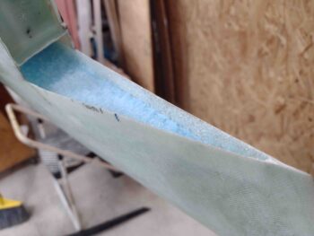
In fact, to give myself a head start I went ahead and took my flat Perm-A-Grit sanding tool and created about a 1/16″ to 3/32″ gap on the outboard lower winglet to bottom rudder seam… sanding this edge downward, taking down the edge a bit of the lower winglet (pic below). Once I did this, all the sanding was on the progressively forward edge of the inboard bottom rudder (pic above). Essentially creating a slight upward curve of the bottom rudder edge as it goes forward.
I then checked my angle on the rudder outboard extension. I will note that as I write this post I referred to the Hight Performance Rudder plans and it shows the angle at the very top of the rudder, so I might try that out of curiosity… because what angle are we actually measuring? There is clearly a significant curve of the winglet, as it has a camber, so do we extrapolate from center line? Hmmmm?
Regardless, my goal here was to have the rudder able to swing outboard free and clear with its only constraint being when the Internal Bellhorn hits the inside wing end. The eventual determinant of max angle will be cable length (to a degree with the spring in the mix) and rudder/brake pedal configuration. I just don’t want to possibly tear up the edges of the inboard rudder/outboard lower winglet by having these things scraping against each other… or worse, jamming at “full” rudder swing out.
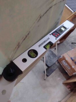
For reference, at about midpoint between the lower and middle hinges, my measured rudder out angle is 29.2° so I’m calling it good… except I think I still have about another 1/4″ before my Bellhorn arm tip kisses the wing rudder cable conduit opening.
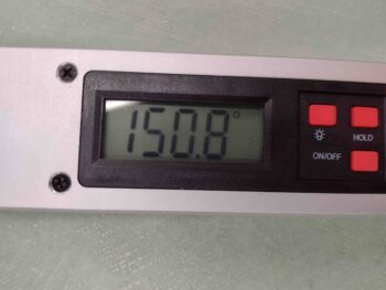
Again, for both reference and curiosity, my right rudder out measurement is 4-1/8″.
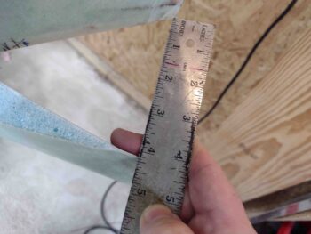
Compared to the left rudder, which is 4-1/4″… clearly a bit more aggressive sanding on my interference edges over on the left side. Meaning my rudder Bellhorn arm is a bit closer to the wing edge.
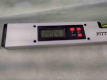
Sorry for the blurry pic, but the info remains the same: left rudder out angle is 30.6°, measured in about the same spot as the right rudder.
I have a bit of a unique situation that makes my whole rudder cable install require a significantly higher level of precision than a “normal” rudder cable install. I think in the end it will be very beneficial and an operational plus, but it really almost eliminates any room for error on getting the Bellhorn cable end AN111-C3 swaged into place.
What am I talking about? Well, when I first started building, one of the Old Guard builders told me what rudder cables to buy, and to order them pre-terminated from Aircraft Spruce. Starting out, when you have only a basic understanding of all things build-related advice is great, but what you don’t have is the experience to exactly understand what skills and knowledge is required to complete the task.
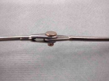
Here are my pre-terminated cables that make up my engine compartment rudder cable quick disconnect.
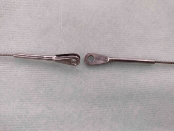
The pre-terminated cable ends would eliminate the need to make up the plans cable attach fitting in the engine compartment.
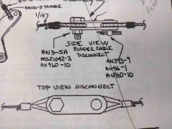
Clearly with my pre-terminated rudder cables meeting in the engine compartment, it means that I have to ensure I have my ducks in a row cable-length wise going out to the rudder and forward to the pedals, and spacing wise inside the engine compartment to allow for cable movement without jamming up on the Nylaflow conduits on either side.
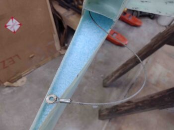
Since I have never swaged a cable before, I simply used a spare AN111-C3 at the very end of the untrimmed rudder cable to get an idea of what I was doing with this whole swage thing. I’ll simply lop this off and terminate at the correct cable length after I test out the rudder pivot with the cable connected to the Internal Bellhorn.
My swaging, although cumbersome with the required wrench work. seemed to go fine.
You’ll note that I thinned down the AN111-C3 cable bushing with the Dremmel tool for some reason… why? Well, in talking to Chrissi from the Cozy Grirrls a while back, she warned me that these AN111-C3s are a hair over 0.15″ thick, while the spacing in the Rudder Bellhorn for it to get mounted into is only 0.13″. Clearly over 0.02″ needs to come off somewhere for this bushing to work.
This was a test run in part to check out how a thinned AN111-C3 would swage and hold on the cable. My final determination is to take a bit off the inside of each Bellhorn arm tab and then a bit off of each face of the AN111-C3. That leaves a hair more meat on the AN111-C3 bushing faces. Yep, always something!
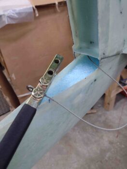
[Note the carved out foam on the lower winglet… see below]
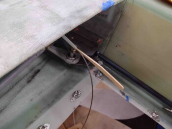
The good news is that apparently my left Internal Rudder Bellhorn configuration is good enough to give me full, unhindered left rudder pivot action right out of the gate.
BTW, to take the pic above I jammed a soft split wood stir stick into the Nylaflow to keep the rudder cable from slipping back outboard.
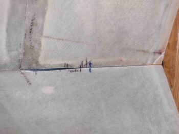
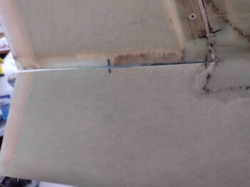
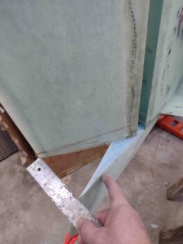
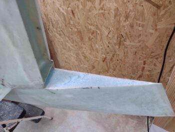
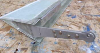
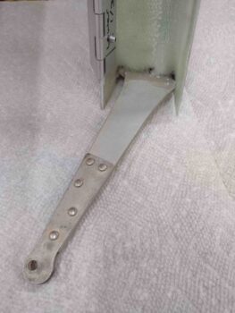
Although I carved out the foam on the last exposed foam face in my rudder/winglet setup: the lower winglet, I didn’t highlight it on the left side. Here we have the same area on the right lower winglet with the foam removed for glass prep. Tomorrow I’ll prep the glass edges and lay up a couple plies of BID in this lower trough.
A task I also did on the left side but am just now documenting for the right side is removing all the tape and cleaning up the glassed edges of the Internal Rudder Bellhorn arms.
Tomorrow I’ll continue my quest to get the rudders rigged and functioning with the wing side rudder cables installed. The fuselage side rudder cables will be completed within the next few weeks when I get some brackets made up for the rudder cable conduits exiting out of the CS spar on each edge of the firewall.