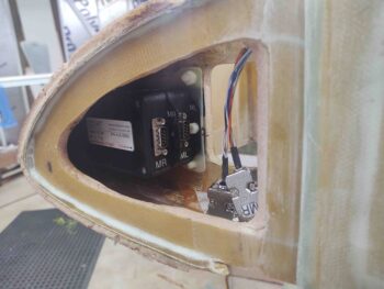
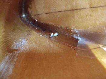
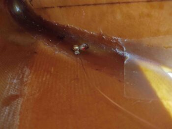
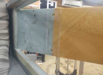
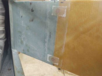
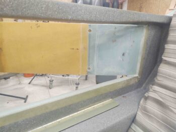
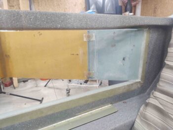
I started off today by sanding down all the glass edges of the left strake OD rib layup. I hate putting my hand into something on this plane only to have it extract a surprising blood sacrifice for doing so… thus I wanted to make this compartment hand friendly.
I also wanted to ensure the GRT magnetometers would fit unhindered, with no blockage or snags that may have been introduced by the new layup.
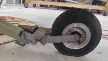
I then got to work on the strake fuel tank drains. Before I get into discussing those, I wanted to show a quick shot of the approximate position my front landing gear will be in when I check the fuel for water contamination. I didn’t want the plane to be in full grazing position, and actually wanted the resting foot about an inch off the ground. Thus within seconds I can have it either in full graze, on the resting foot, or just a few inches higher for ingress into the plane or moving it.
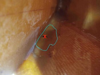
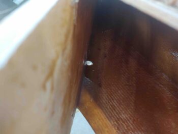
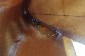
With the plane in the grazing position above, I then did the marble trick to test out the low spot of the strake which per plans designates the position of the fuel drain. But then curiosity got the better of me and I subsequently poured some water in the leading edge to see what that might show me.
Interestingly, the water did tell me something. Not so much on the right side, which confirmed that the marble –which I dropped in there multiple times– did come to rest in center mass of the small water puddle (black mark for marble, red X for water). So I decided to place my fuel drain here.
But the left side was a bit different. The spot where the marble came to rest consistently (black mark/green arrow) was towards the front of the water puddle, whereas my take on the center of mass (red X) for the puddle was a bit aft. And more in line with what was going on over on the right side.
Thus, for more symmetry between right and left I decided to drill the hole on the left side strake at the puddle center mass a little over 1″ aft of the marble resting spot. This puts both left and right fuel tank drains within a half inch of each other when measured from the center of the leading edge.
 I took the first plunge, literally I guess, by drilling the drain hole in the right strake first.
I then placed the fuel drain block up to the hole, sited down the hole from the inside to get the best centered alignment on the actual drain before marking the outline of the drain block on the external strake leading edge foam.
After cutting out the foam, I then test fit the drain in its aluminum block into the foam.
I carefully drilled up through the #8 tapped hole with a small diameter drill bit to then widen it out for the #8 screw. I then secured the terminated internal fuel tank ground wire to the fuel drain block with the #8 brass screw.
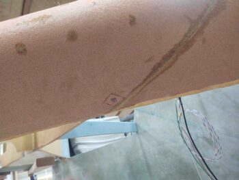
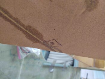
I then repeated the same process on the left side. Here we have the fuel drain block marked and ready for cutout.
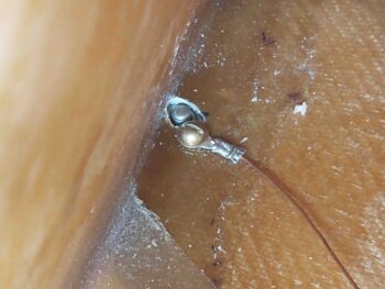
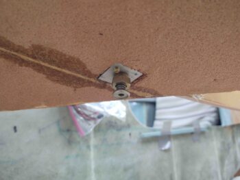
And the internal fuel tank ground wire attached to the fuel drain block via the #8 brass screw.
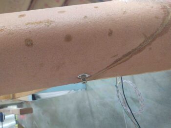
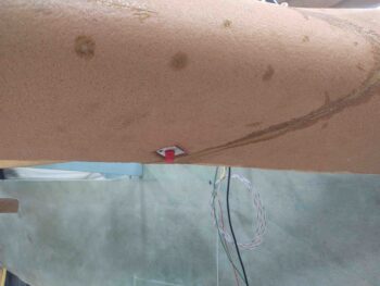
A shot from the outside. Note that the brass screw is a bit long, so I marked it to be shortened.
A bit later, after both brass screws had been shortened, I floxed in the strake fuel tank drain blocks into their respective leading edge notches. Here we have the left side.
The thing I really like about this design and configuration is that the screw makes it easy to get the block into the cut foam notch nice and securely… no messing around with trying to apply pressure to keep the fuel drain block in place since the screw does all the work.
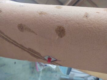
Here is the right side fuel drain block, floxed in place. Obviously I removed the actual drain assemblies and put a protective red plug in place to protect the threads from flox.
In addition, a little while after I floxed in both side fuel drain blocks I performed a continuity test to ensure I was getting an electrical connection from the drain block to the ground wire. Both sides checked out good.
I left the floxed fuel drain blocks to cure while I then measured and drilled out 1/2″ holes into the baggage area side of the BAB baffle for the Atkinson fuel site gages. Note that I didn’t drill all the way into the fuel tank side, leaving the tank side glass intact for better integrity and leak avoidance.
I then filled these future hard points with as wet as flox as I could without it running out all over the place. I then peel plied the floxed hard points.
Here’s right side as well. First the pockets drilled and cleaned out.
And then floxed and peel plied.
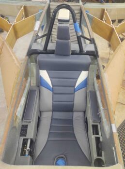
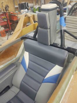
With the epoxy based tasks out of the way, I then cleaned, organized, and vacuumed out the front seat area to test fit the upholstered front seat cores.
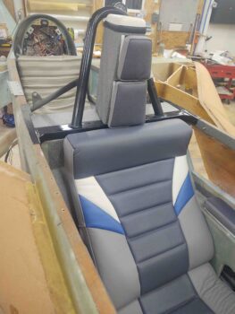
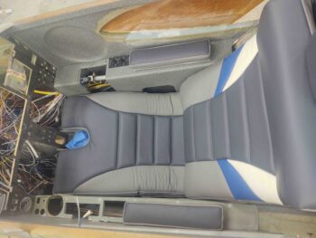
I have to say, everything fit nicely and I’m very pleased with how the seat cores, both front and aft, came out.
Here’s a shot of the forward lower seat pad.
And another headrest shot. Note that the headrest pads are temp taped in place, so they are not aligned as they would be when permanently installed…. just as with the headrest pad I mocked up on the back seat.
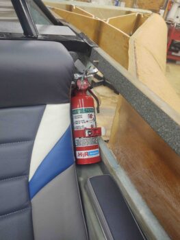
I of course wanted to check out the fit and look of the front seat cores, but another reason I wanted them in place was to see if my fire extinguisher was going to fit in the upper left corner, alongside of the seat, since this is where I decided the optimal location would be for it.
Thankfully it fit just fine.
Tomorrow I have a few more minor details to attend to, but then plan on getting the rib-top T-hats started. At least on one side.

