
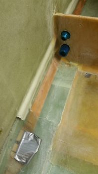
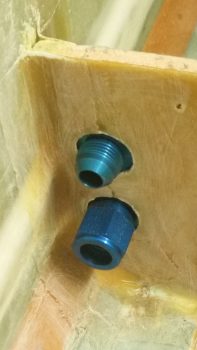
Today I started out by cleaning up the 2 oil line reducer fitting mounting holes in what makes for a mini-bulkhead for the pair. I then test fitted the oil heat line reducer fittings in the holes.
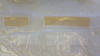
I spent a good bit cutting out 4 prepreg setups of BID and BID/Kevlar tapes for the sump left wall installation.
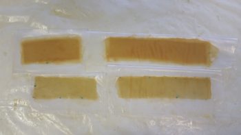
Here are the tapes wetted out with E-Z Poxy.
I then floxed/micro’d and glassed the sump left wall into place.
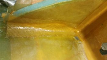
I then peel plied all the sump left wall install layups.
Another shot of the sump left wall install. Immediately following taking this pic, I threw these layups under heat lamps.
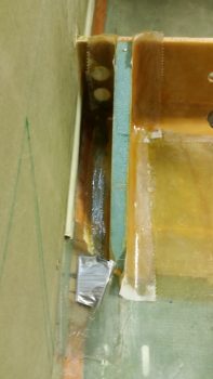
I then pretty much repeated the process — sans Kevlar, and a second ply of BID– to flox in and layup the corner tapes to install the sump middle rib.
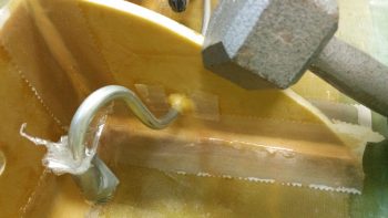
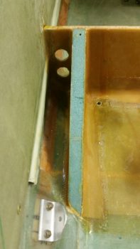
Here’s a closer shot of the flox & BID around the left tank fuel line coming through the sump middle rib.
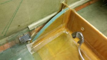
And a shot of the other side.
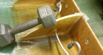
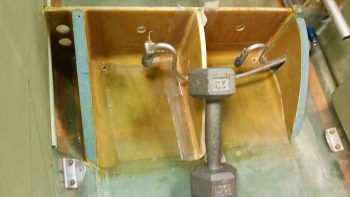
And finally, a shot of both outside walls and middle rib. As of now, I just have the right wall to install.
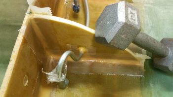
And here’s a shot of the fuel sump left wall after I pulled the peel ply and cleaned up the layups.
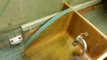
Part of that cleanup included, once again, cutting the freshly laid up glass out of the oil heat lines reducer fittings.
Tomorrow I plan on glassing in the sump right wall, and that will be pretty much it since I have plans for tomorrow evening.