
Today I took the 2x boards and weights off the end of the front side BID layup on the fuel sump front wall. I have to say, the weights worked great to straighten out the sump front wall.
I pulled the peel ply and razor trimmed & sanded the edges. I then cut out the hex holes on the left side of the wall for the oil heat line reducer fittings. Also, I drilled the two 11/16″ holes for the low level fuel sensors. Finally, I added a spot of micro in the areas where I had the toothpicks holding the Nylaflow in place.
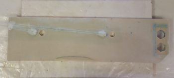
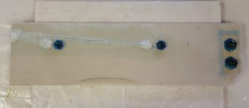
I then test fitted both the oil line reducer fittings and the low fuel level sensor fittings.
I ran out to Harbor Freight today to get my new “Fein” saw, which has increased in cost by a whole $5! (bummer). I picked up a few other things I needed for the build and headed back home. The traffic was unusually heavy today, so it took well over an hour longer than I expected.
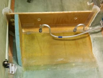
Upon returning home, I checked out the new “Fein” saw and actually used it to cut a small notch in front right sump wall extension piece that will adjoin the front wall piece that I’ll be glassing in… the notch is for the 2 Nylaflow lines so that they can smoothly transition out of the wall. BTW, if you caught the Nylaflow lines’ positions, you may have noted that they are at the same level (waterline) as the small wire bundle that will be traversing down the side of the fuselage (as could be ascertained by where I drilled the hole in the front right sump wall extension piece). Thus, the position of the Nylaflow puts them in the perfect spot to merge right into the small wire bundle.
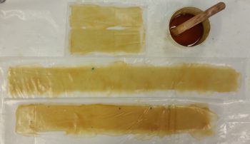
After I sanded and prepped all the areas that would be receiving glass, I then spent a good 45 minutes cutting Kevlar, BID and plastic to make up BID tapes and a BID/Kevlar tape for glassing in the sump front wall. After I got all the prepreg setups ready, I mixed up some E-Z Poxy epoxy and wetted out the first few BID and BID/Kevlar tapes (the one with Kevlar went on the inside of the tank along the junction of the floor and the front wall).
Over the next 3 hours I proceeded to glass in the fuel sump front wall.
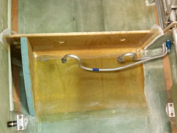
It’s definitely not the prettiest or smoothest layup I’ve done, but so far I think it’s solid as far as meeting fuel tank requirements. Here’s a shot from the front looking aft. I should note that I placed the left sidewall piece in its spot merely for spacing & alignment, and if you look closely enough you can see that I put a nail through the top corner of the sump sidewall into the sump front face to secure it.
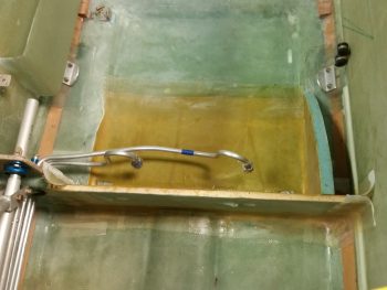
To make things EZ I of course used E-Z Poxy on the entire layup, including the left side extension tying the sump front wall into the left sidewall. After I got all the BID (and Kevlar) tapes laid up, I the peel plied all my layups and took care to keep the internal tank layups very wet. You may have noticed that the outboard sides of the inside corner tank tapes seem to curve up (i.e. “smile”), while towards the center it “droops” down. I did this on purpose to not completely cover up the fuel drain valve holes.
Tomorrow I’ll shoot to get all the sump walls glassed in, and then start working on the hardware for the fuel sump top inspection hatches.