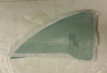
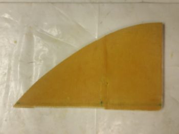
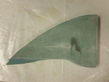
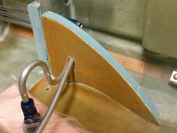
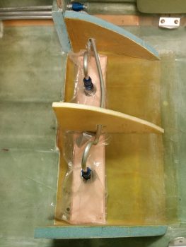
I started off today glassing the outboard/exterior side of the fuel sump’s right wall. I then peel plied the 1-ply BID layup.
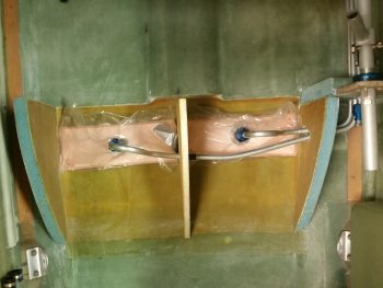
I also pulled the peel ply and cleaned up the layup on the right side of the fuel sump’s middle rib. After I cut the notch for the left sump fuel line access, this will be ready to install.
Quite a few hours later I pulled the peel ply, knife trimmed and sanded the edges on the outboard/exterior side layup on the fuel sump’s right wall.
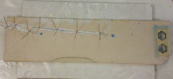
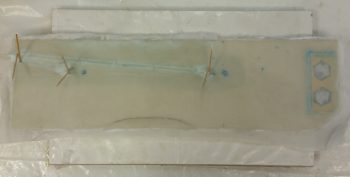
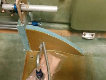
I finally decided after assessing the oil heat feed and return lines that I am going to run them through the fuel sump front wall’s left extension tab. There won’t be a lot of space for working and mounting these lines, but once in they should be good for quite a while. I was going to use 1/4″ Finnish Birch plywood, but since I have some spare bits of H250 high density foam on hand, I decided to use it instead. I made two hex holes in the H250 to flox in the AN -8 (1/2″) to AN -6 (3/8″) reducer fittings. This is required since the oil heat exchanger only comes with -6 fittings, so at some point each of the lines needed to be reduced/expanded to work. And that point is here, about a foot away from the heat exchanger.
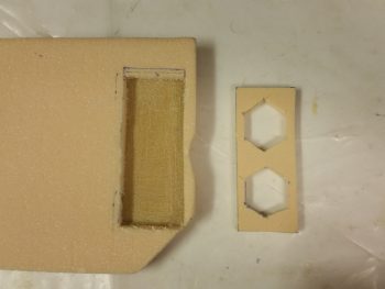 I then micro’d in the H250 reinforcement foam and also the 3/16″ Nylaflow lines that the low fuel sensor wires will use to exit the front fuel sump wall. To be clear, I didn’t put in these Nylaflow lines just to be fancy or make it look cool. I wanted to ensure that these wires in an area that is subject to feet sliding against it –literally every time the GIB gets in or out of the airplane– were protected.
I then laid up 1 ply of BID across the entire front face of the fuel sump front wall. I also added a reinforcement ply of BID both over the left fuel low level sensor mounting point, and all around the entire Nylaflow line area, which includes the right fuel low level sensor mounting point.
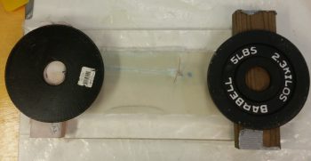
When I glassed the aft / interior fuel sump side of the front wall, it had a distinct bow to it afterwards. I wanted to get the fuel sump front wall as straight as possible, to facilitate ease of glassing it in, so I weighed down each side with taped 2x pieces of wood with a 5-pound weight on each one. That should do the trick!
I actually did this earlier in the day, but since my blog posts are getting a bit long, I decided to put it here for topic flow. To finalize the fuel line installation from the Pulsation Damper aft into the Hell Hole, I need to know what clearance I have. Yes, knowing how to get around or skirt by the GIB right armrest storage pocket is great, but there’s another factor at play here: the armrest itself. I decided a week or so ago that since I had fuel line fittings that I may need to get to after the plane is operational (plus, 98% of my wiring runs are on that side) that I should make the right GIB armrest removable.
First thing this morning, with the same MGS epoxy that I used to glass the outside of the right fuel sump tank wall, I filled in 3 divots with flocro that I had made previously in the exact spots I had chosen to be the screw hardpoints on the armrest.
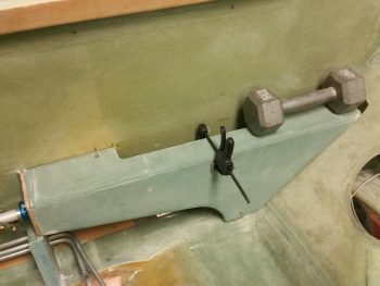
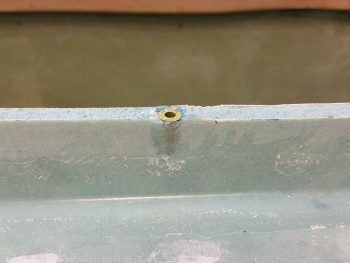
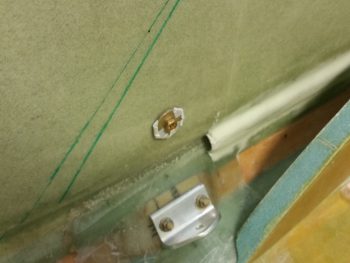
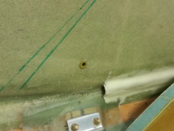
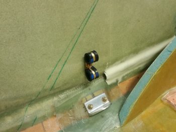
Realizing that with a lengthy storage pocket the possibility for vibration between the top edge of the pocket and the inside edge of the now cut armrest was very likely, I decided to mount a screw hardpoint at the center point of the pocket. I determined where the hole should be, and mounted a small RivNut there with flox. Thus the clamp you see in the pic, holding the storage pocket firmly against the armrest to obtain the correct spacing on the hardpoint.
[oh, yeah, I cut out the notch for the storage pocket . . . and burned up my trusty “Fein” saw in the process . . . but it pushed on until the very end! Literally smoking as I put it out in the driveway and opened up the garage door to clear out the stench of its gruesome death! Well, back to Harbor Freight to plunk down another $14.99! Hopefully this next one lasts 6 years of punishing work like this one did . . . a moment of silence please].
Since I only had 3 drilled brackets from my right front armrest installation frenzy, I decided they would do fine for now. I do intend to install at least 2, if not 3 more mounting brackets. One off the front CS118 control stick bulkhead and one off the middle of the aft angled part of the armrest, about mid-point onto the GIB seatback.
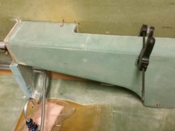
On the left you can just the midpoint screw in place, and on the right I snapped this pic as I was removing it to show a clear shot of where the midpoint screw will be installed.
And here’s the midpoint RivNut hardpoint secured in place on the right GIB armrest with flox.
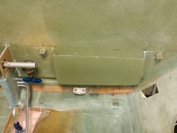
Here’s a shot of all the new right GIB armrest brackets in place, secured with flox. Again, I want to give a shout out to Dave Berenholtz for doing the 1/16″ thick aluminum angle mounting brackets. I honestly would have never thought seriously about using aluminum . . . brilliant Mate!
Also during today’s adventures I floxed a RivNut hardpoint in place over the left GIB seatbelt bracket for the oil heat lines.
Here it is after cure…. looking a bit lonely, eh?
So I gave it some friends. . . 2 Adel clamps for the oil feed and oil return lines to/from the oil heat exchanger that will reside on the left sidewall, immediately aft of the pilot’s seat, about midpoint up the wall.
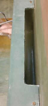
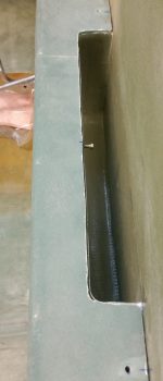
For the final push of the evening, I then set my sights on cutting out the fuel line notches in the fuel sump right wall and middle rib. Below you can see that I’ve struck gold! I started on the freshly glassed exterior side of the right wall and started removing the plug that provides access to get the fuel lines into the wall before the plug goes back in, and it all gets slathered with all varieties of flox –slurry, wet, paste, dry– and sloppy wet bid tapes.
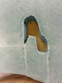 I then mocked up the right wall by setting it in place. I did have to spend a good 10 minutes fine tuning the fit by some judicious sanding, but in the end . . . like a glove!
Here you can see the lower foam/glass plug in place that will help seal up the fuel line access hole.
I then did pretty much the same thing with the middle rib/wall by cutting out the access notch to slide the rib in over top of the left fuel line. Again, I configured the left fuel line going through the right sump tank to support this oft heard statement when flying: “Passengers: Please keep the aisle clear of any fuel lines!” . . . yes, in short I didn’t want any high-heeled Vixen (you know who you are!) digging their heel into my fuel line, or any of my other ham-fisted, Neanderthalic friends (and you guys know who you are too!) doing the same —well, Good Lord, hopefully not with high heels! … haha!
Here’s one last shot of all the fuel sump walls glassed and ready for install. With the front side of the fuel sump wall curing tonight, I should be ready to start assembling this beast within the next day or so.
Yes, tomorrow the fuel sump tank work continues, so ‘Tune in tomorrow folks for yet another fun-filled adventure!’

