
I started out today by pulling the peel ply and trimming up the edges of the layups on the wall sides that essentially make up the left sump tank, left & middle walls.
I then promptly glassed the right side of the middle wall, or sump rib, with E-Z Poxy to get it curing.
I then glassed the outside of the left sump wall using MGS, since this wall will not be in contact with fuel… hopefully!
When I did this layup, I also glassed a strip of BID on the bottom of the GIB right armrest storage pocket going to the sidewall. Once cured, the GIB storage pocket will be glassed in once and for all.
 I then marked up and did an initial cut on the right side wall to start the trial & error process of getting it to fit.
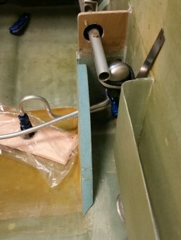
Here I’m about halfway through the process of fitting the right sump wall to the sump / fuselage floor.
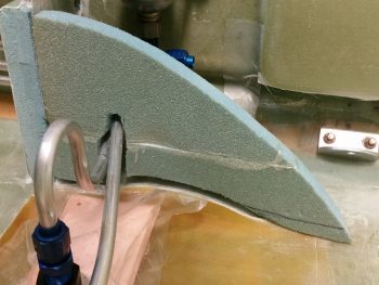
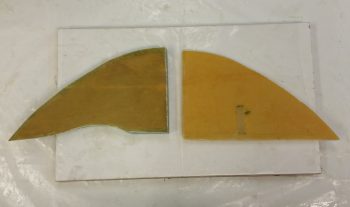
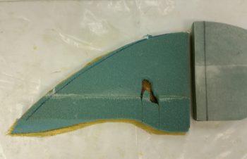
And here’s when I finally got the shape along the bottom of the sump right wall dialed in.
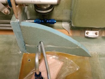
Here’s an aft shot of the fuel sump’s right wall. Note that you can also see the fuel pulsation damper mocked up in these pics as well.
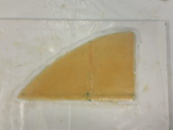
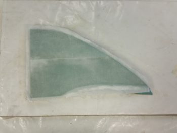
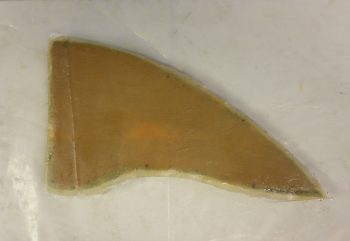
Once the shape of the right wall was good, I glassed it with a ply of Kevlar first, then a final ply of BID, just like I did with the inside layups of the other walls that make up the exterior perimeter of the sump tank.
One thing I was going to account for that slipped my mind until after I hurriedly glassed the interior side of the right sump wall, was that this wall needs to be a bit shorter due to it butting up against the back side of the right front sump wall extension. I was so dialed into getting the difficult shape on the aft side of the wall completed, that I missed the front edge needing to be back 0.55″. Since I had already configured the right side wall, I was going to merely trim the aft edge so it’s profile would match the other 2 walls. But again, I jumped the gun in glassing the right sidewall so I didn’t get it done.
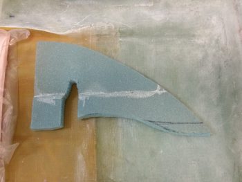
Fast forward many hours later, and I marked the left wall with 0.55″, aligned the two sides and then marked the aft/top of the right sump. I trimmed the right sump wall immediately after this pic was taken.
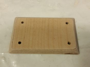
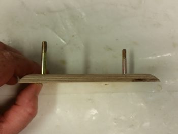
As the interior layup of the right sump wall was curing, I decided to knock out making the oil heater pump base. I started with the 1/4″ Finnish birch plywood plate I cut out the other day. I rounded over the edges and then drilled 4 x 3/16″ holes.
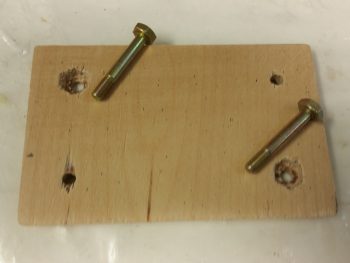
I then marked the heads of the only 2 AN3-12A bolts I have onto the back of the mounting bracket and dug the wood out to keep the bolts from spinning.
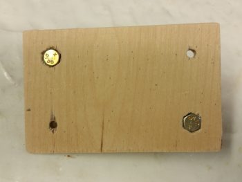
The bolt heads are flush with the bottom, can’t spin, with still a good amount of wood to keep them in place. Still, this plate will get about 5 plies of glass to hold it in place.
Here’s a side view showing the bolts in place.
Since I didn’t have any more AN bolts, and I wanted to get this mount finished, I stole the two 1-1/4″ bolts from the fuel pump and mounted them in the oil pump mounting base. I then taped up the bottom of the vibration mounting pads, floxed the bolts in place and then set the oil pump in place over the floxed bolts.
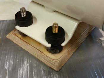
And here’s a couple more shots of the oil pump on its mounting base.
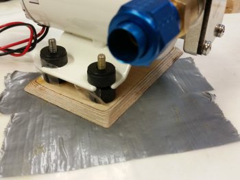
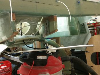
I then used the oil pump attached to its mounting base to figure out where in the world I was going to mount this thing in the Hell Hole. Since I just recently discovered that it is best to mount it horizontally (interesting, but that’s what it says!) I found a spot centerline of the aircraft, immediately forward of the gear bow and just aft of the GIB seat.
This all ties into the sump in that before I glass the front side of the fuel sump front wall, I need to know if I’m going to mount the oil heat line fittings into the LEFT sump front wall extension.
To figure out my oil heat oil lines, I needed to make some. So I did. I made the feed line that feeds the oil to the heat exchanger from the oil pump. It all looked good on the top side . . .
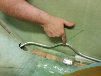
. . . as you can see here . . .
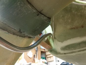
But since I don’t have a 1/2″ tube bender, I resorted to a spring kit for bending the 1/2″ tubes. The spring works well enough on simple bends, but it just can’t handle really tight turns without crimping or flattening the tubing — as you can see in this real tight turn to the right.
I’ll assess further, but right now I’m thinking at least the oil feed line will most likely need to be a braided cable to provide me the flexibility that I need.
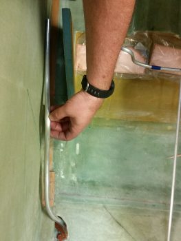
With that, I then made up an oil return line. Since it doesn’t need to make a hard right turn to get to the oil pump, I didn’t think this one would have as much of an issue as the oil feed line. And it appeared not to.
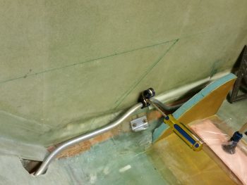
One interesting point in the pic below: I played around with the spacing and tubing run for a bit before deciding on exactly where I wanted the Adel clamp to be located to hold the 2 oil lines (feed & return). Well, I reached into my pocket to get my trusty Sharpie, but, uh, no Sharpie. So, I picked up a small Phillips screwdriver and gave it a nice sharp rap to make a mark…. well, it was a bit harder than I thought and it made a nice dent in the wall. So, another wiggle and another rap, and in she went…. I guess this will be a RivNut hardpoint vs a Clickbond!
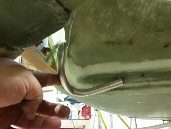
A shot of the oil return line from below.
For now I’ll just count the oil return line good, and then later when I finalize the firewall configuration I’ll cut the oil return line and terminate it with a fitting.
Tomorrow I’ll continue working on the fuel sump. I’m hoping to have it done in the next few days.