
Today I started out by pulling the peel ply off the left strake bottom skin foam core baggage area that I glassed with one ply of BID using MGS epoxy. I then razor trimmed the edges.
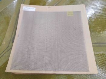
I had planned on doing the same layup on the right strake bottom skin foam core baggage area AND glass the remainder of the left strake bottom skin foam core inside, but I ended up going on a wild goose chase looking for my fuel tank drain stainless steel “finger-strainer” mesh to ascertain how it would need to go in before I glass the bottom skins.
Why?
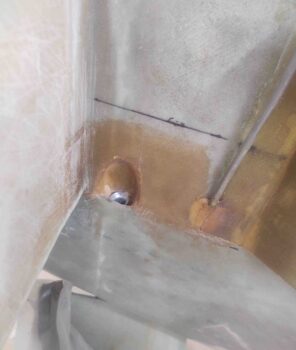
Well years ago Mike Beasley gave me a good piece of advice when he told me to create a small channel in the foam before glassing so that when the strainer gets floxed into place it doesn’t essentially create a speed bump with flox piled above the surface of the tank floor where the strainer is secured. Good advice and something I am taking into account.
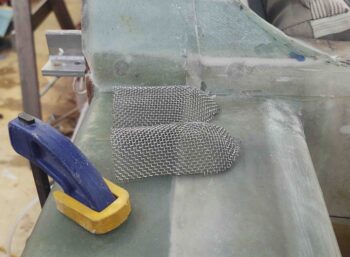
However, since the strainers that I came up with are a bit smaller than the half moon type other builders put on the floor of the tank, with the stock plans drain hole —mine is at the bottom of a small fuselage sidewall alcove— I decided to simply mark and Dremel a narrow half moon channel in the fuselage floor after glassing to meet this requirement.
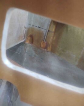
With such a small diameter half moon, combined with the flox and supporting glass in that area, I don’t think I’ll be risking any major structural issue by doing so.
I did end up doing some impromptu cleaning and organizing of the shop while I looked for the tank drain mesh, but it put me a few hours behind.
As I describe above, I ended up making my tank drain “finger strainers” a bit smaller than most builders do, but still with more surface are than the original flat version I had planned on just slapping over the drain alcove. Still, since I’m not making a channel in the foam for the strainer I didn’t need to wait to prep the right strake bottom skin foam core aft edge.
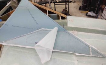
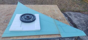
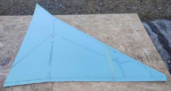
Here it is before I did anything to it.
I then marked the aft edge for trim. Having learned my lesson to just “follow the plans” I simply marked it at 1″ and pressed on.
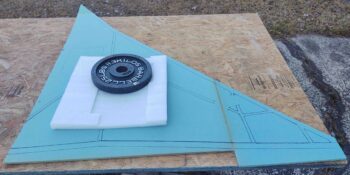
Here we have the aft edge trimmed to 1″ aft of the face of the CS spar.
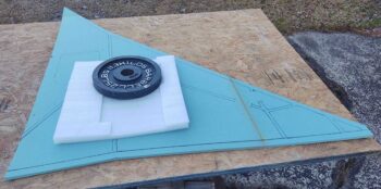
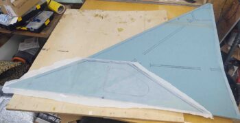
I then beveled the aft end to match the bevel on the bottom edge of the right CS spar.
As I did on the left side, I then laid up a ply of BID (using 3 “scrap” pieces) using MGS epoxy, and then peel plied the entire layup.
I then left that to cure overnight. I had planned on at least cutting the glass for the left side, but it was late and the earlier goose chase had left me feeling a bit wore out to press forward. I’ll hit it fresh tomorrow.