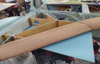
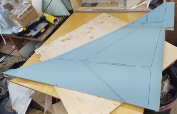
Today was all about working on finishing up the fitting, cutting and construction of the strake bottom skin foam cores. I also did a lot of assessing and trial fits of both the GIB strake windows and the fuel site gages.
Both the GIB strake windows and fuel site gage positioning are both heavily influenced by a specific GIB passenger body part: the elbows. Precisely that I modified the position of the BAB baffle to allow for more elbow room into the strakes, then I have to allow for and reserve that aft triangular corner piece of real estate for the GIB’s elbows. This pushes the aft edge of the window just a hair forward and the fuel site gage as outboard as possible while still being able to see the top of it from standing outside the airplane.
Obviously the passenger most likely won’t be sitting in the aircraft during ground refueling ops, but a key consideration in my configuration is allowing my fuel site gage cameras to get both a good viewing angle of the fuel site gage and also not have the view fully obstructed by the passenger’s elbows. So again, the more outboard, within reason, the better.
After sitting on my keister in the back seat for a good while, and my initial rough outline of the GIB strake window made, I then took the lower left strake skin foam core outside for a trim.
Here I’m trimming the aft edge to length.
As you can see here.
I then beveled the aft edge at 1.1″ this time. Of course after I checked it I like the fit 1.0″ better, so I’ll be tweaking it just hair. Should’ve just followed the plans eh?
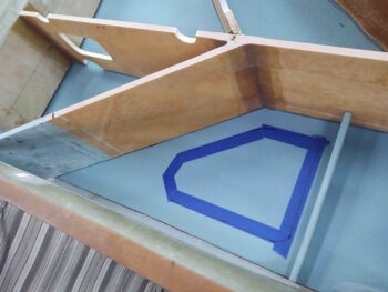
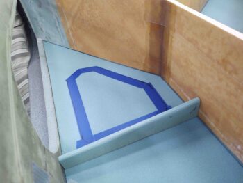
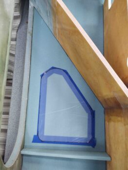
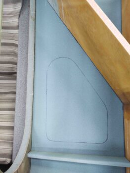
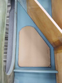
I then drew my actual outline (initial) of the GIB strake window.
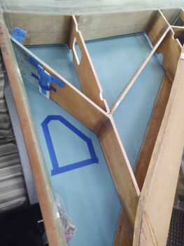
Here’s another shot. Note the short cross foam piece that connects the fuselage sidewall to the R23 rib. This diminutive guy will serve a few purposes. First, it will keep stuff from sliding back onto the window during flight. I know in the back of Marco’s Long-EZ during Rough River trips we have a lot packed in there, and nothing really to keep stuff secure and from sliding aft over the window. Nothing horrible or overly annoying, but it would help to have a “catch” if you will.
Next, with the GIB elbow room mod taking the BAB a lot further aft, to help with loads between strake and fuselage I figured I’d add this in for a little added strength. I’ll also do another “mini-baffle” like this at the top about 12″ forward of this one. On the left that will be even more critical since pax often ingress/egress the back seat over and on the left strake top.
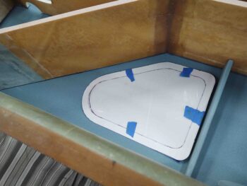
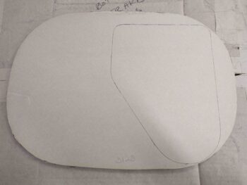
Since I didn’t have tracing paper I used clear plastic to mark out the interior outline of the GIB strake window.
Of course airplane building and feature design is all about trade-offs and compromises. I would prefer to increase the size of the window going forward a bit, but I want that mini-baffle there in that spot and symmetrical both left and right. I’ll most likely install an O2 bottle in the baggage area, mounted to the “external” sidewall, so I need most of the fuselage sidewall from aft-to-forward strake opening clear.
Moreover, as was pointed out in a CSA article on these things, the GIB strake windows tend to be a bit heavy. In the article the builder went with 1/8″ plexiglass simply because it was strong enough and, moreover, it was clearly half the weight as a 1/4″ plexiglass. Well, my strake windows split the difference at 3/16″ thick, and these are not feathers. Total added weight for the size windows I have shown here will be about 1.5 lbs. Obviously bigger windows means more weight.
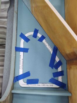
I then transferred the viewing area of the window (inner line), which is also the cut line on the bottom, external side of the strake… once it’s finished for paint. The outer line is the size of the actual “plexiglass” (mine are airline windows) that will then have BID securing them in place up to the inner line. For more viewing area, as in a bigger window, I didn’t follow the recommended 1″ border as proposed in the CSA article, but rather cut the border down to 0.7″.
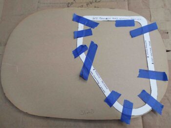
I then finished up my GIB strake window template by cutting out the center area. Again, the interior template line actually denotes the exterior/external cut line (bottom strake surface) where as the outside template line is for inside the baggage compartment.
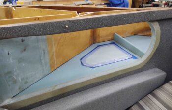
I then marked the interior template line on the foam. This gives me the location of the window and an idea of the viewing size. Plus, by only marking the inner line if later on I get a wild hair I won’t do anything stupid like cut the outer line all the way through, which is not how the install process is supposed to go!
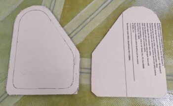
To get the window weights and also have the them ready for install, I used my template to mark the outline on the first of two of my surplus airline windows.
Read to be cut.
I then cut it out using my Skil saw (yup!).
And here’s the second one cut out as well.
With my GIB strake window planning machinations out of the way, I then glassed the baggage area floor of the lower left strake skin foam core. Since it was later in the evening and the weather is a bit chilly right now (slightly cooler shop), and plus liking the wet out characteristics on a large layup that will get entirely peel plied, I went with MGS vs EZ-Poxy for this layup. Clearly I plan on doing the remainder of the left strake bottom interior skin with EZ-Poxy.
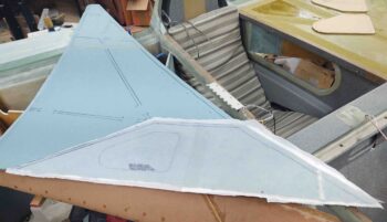
My last task of the evening was to knock out the fitting, cutting and assembly of the right strake bottom skin foam core. I have to say I’m very pleased that fitting the bottom skins really isn’t that much more difficult than the top skins, as I had suspected it might be.
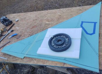
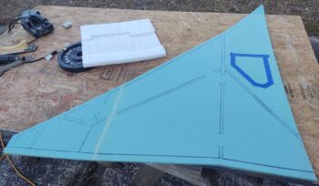
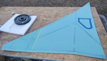
A bit later I micro’d the forward and outboard foam triangular pieces to the larger main foam piece to make up the lower right strake skin foam core.
I hen left it to cure overnight. Tomorrow I’ll trim and shape the aft edge and start the 1-ply BID layups on this skin core as well as finish up the left bottom skin foam core.

