
Today I focused on mounting the EFII fuel pump and its pre-filter. I played around with the configuration for a bit before finally narrowing both components’ locations as shown below.
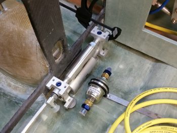
With the existing fillet at the bottom aft of the instrument panel –where it’s glassed to the fuselage floor pan– I needed to have a slight gap between the fuel body and the instrument panel. I thought 1/16″ (0.063″) would do it at first, but it wasn’t enough and still caused the bottom of the fuel pump to kick out aft a little bit, not allowing for a true vertical install. I tried 1/8″ (0.125″) but it seemed a bit too much. I then scrounged up some 0.093″ scrap aluminum to test as a spacer and that did the trick.
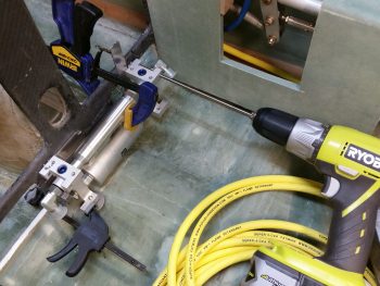
With the position of fuel pump dialed into its final position, I clamped it and drilled the top 2 mounting holes into the lower instrument panel.
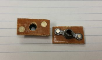
I then made up 2 K1000-3 nutplate assemblies with 1/16″ phenolic.
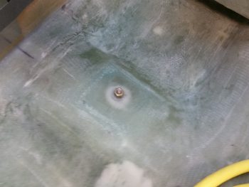
With my fuel pump positioned, I then fiddled around with the pre-filter before I finally figured out its final position. I then marked the spot and 5-min glued a click bond in position (after I prepped the clickbond).
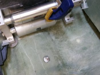
I then laid up 3-plies of BID over the Clickbond after creating a flox transition around its edges.
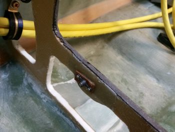
I also floxed in the left nutplate assembly and screwed an AN3 bolt into it to hold tightly in place while it cured. Over on the right side, due to the drilled mounting hole being so low on the lower instrument panel cross frame (top edge of map box/lower edge of leg opening) I micro’d in a half moon looking piece of H45 foam in prep for 2 plies of BID on the front side, and 1 on the aft side.
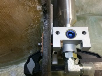
If you’re wondering about the bolt head’s close proximity to the fuel pump frame, and how it can’t possibly turn, you’ve spotted an issue. Tomorrow I need to pick up some hex head socket cap screws to allow them to turn in tight quarters.
I then decided it was time to roll up my sleeves and knock out the hour++ trial and error process of forming respective Devinycell wedges for both the right and left side of the fuel pump. As you can see, these foam pieces will make up the mounting pads for the fuel pump frame’s “feet,” allowing me to bolt in the fuel pump frame on the lower aft sides (vertical bolts) and the forward side (left & right as well) using horizontal bolts.
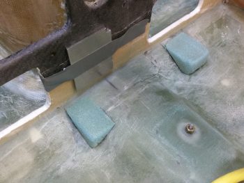
After mocking up the fuel pump countless times, with a myriad of sanding with my Perma-Grit tools (still love those things!) to shape the respective pads, I finally got the shape and positioning I wanted with the pads. Moreover, with the pads in place and the fuel pump temporarily installed, I could checked that there was a decent gap for the eventual mounting of the bigger sized click bonds for the aft side fuel pump mounting.
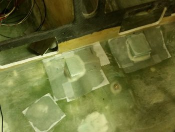
I then micro’d the foam pads in place and laid up 2 plies of BID over each pad. Down in the lower left corner in the pic below is a small square ply of BID that I glassed in placed and peel plied (along with the pad layups) to patch a small divot I had put in the floor at some point… I still had a small amount of epoxy left over allowing me to do this.
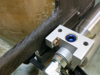
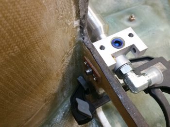
I also floxed the right mounting nut plate assembly into place (after I redrilled the hole) and held it in place with an AN3 bolt while it cured.
Below you can see a shot of the small curved piece of foam I glassed in place to help as a backer for the the right side fuel pumping mounting nutplate assembly.
With that, I did one final check on all the layups, and called it a night.