
I’ll start off by noting that this post covers both today and yesterday.
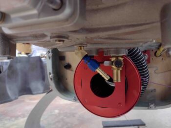
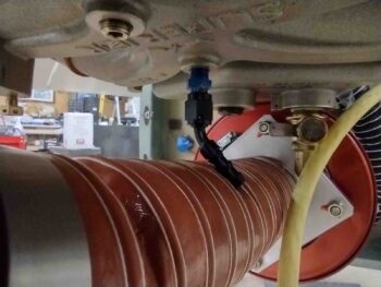
I’ll start off my next informational tidbit with a reminder: my first angled Sniffle Valve setup —to clear the SCEET tube— used a 45º street elbow (which I stole to use on the MAP manifold), with the Sniffle Valve itself cocked at a 45º angle, then a modified brass barbed fitting secured to the Sniffle by a -4 AN nut.
I had the notion, and still do, to clean up my Sniffle Valve setup by using a -4 AN tube nut mounted directly onto the Sniffle Valve with (I hoped) a 45º angled barb to allow attaching the drain tube. But alas, the entire unit is too long and ends up just kissing the SCEET tubing that it is meant to avoid.
Not to be deterred however, in working with Summit Racing for them to send me the correct -3 AN hose for the MAP system, I added a 90º barbed fitting to the order in lieu of this 45º fitting… that I’ll then attach to/underneath the Sniffle Valve to clean things up. I think the 90º fitting should both fit and provide a cleaner install look for the Sniffle.
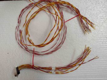
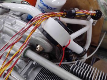
I also mocked up and then cut the pre-populated (IIRC) GRT EIS-4000 wiring harness “B”, which has all the EGT and CHT wire pairs. Each freshly cut side of these wires will terminate into the P10 connector, so I crimped sockets onto the EIS side wire ends and pins onto the motor side wire ends. I also printed off and heat shrink labeled all the wire pairs.
I then took the CHT/EGT wire bundle out to the shop and terminated them into the aft/engine side of the P10 connector.
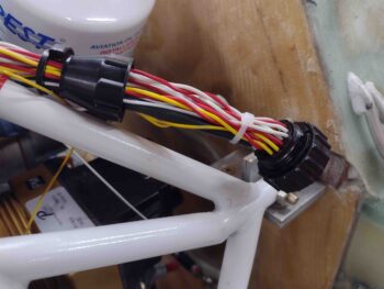
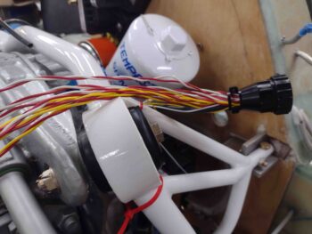
And zip tied all the wires in the P10 connector and threaded on the strain relief backshell. In the right pic you can see the pins inside the P10 connector.
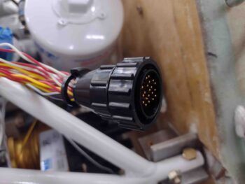
And one final shot of the fully populated engine-firewall P10 connector.
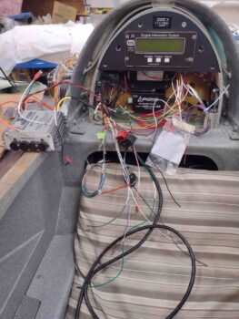
Inside the D-Deck/GIB headrest, I am very, very close to finishing all the wiring connections for the engine electrical components. I did a rather significant update to a number of my wiring and connector diagrams, and have only a few wires to solder and terminate to call the engine wiring complete (again, there are 3 wire/cables that need final install on the bottom of the engine as well). Of course final wiring won’t occur until after the firewall covering is in place and after all the aircraft surfaces micro-finish and painting is complete.
Speaking of the engine electrical components, I spoke with Brad at E-MAG Air regarding my P-MAG to confirm my unit is up to date. Well, the firmware needs to be Version 40 or higher and mine is Version 37. So when I pull the engine off the firewall here in the next few days, I’ll be pulling the P-MAG to send back to E-MAG Air for them to flash the firmware to the latest they have. Actually a good deal to have it done within —hopefully— just a few months prior to first flight.
I also pressure tested a few more engine hoses, with the firewall to fuel pump -6 fuel line (left) passing muster, as well as the oil heat oil return line (right) doing fine as well. I also pressured tested the longer oil heat oil feed line (from oil sump to oil heat oil pump) but don’t have a pic of that one… it passed as well.
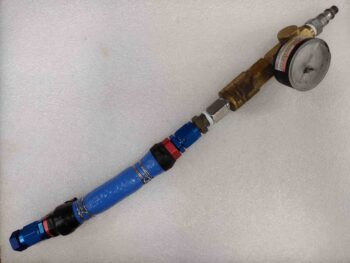
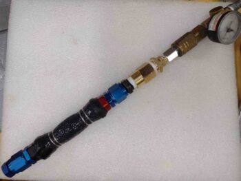
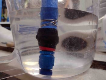
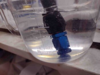
You may have noticed that I wrap the seam of the fire sleeve of each hose with electrical tape. This is simply to keep the lining of the fire sleeve from getting wet.
Tomorrow I plan on finalizing all the component wiring inside the D-Deck to be as prepped as able for engine install. I have not prioritized finalizing the EGT and/or CHT installs until after I get the exhaust pipe clearance issues resolved (coming soon). Also tomorrow I plan on finishing up as much as possible on the engine fuel hoses.