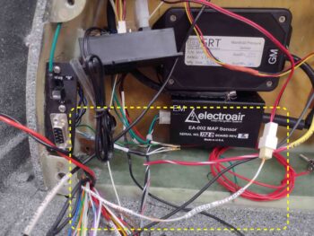
Today I finalized all the wiring for the GRT EIS-4000 and D-Deck components. The one bit of wiring I have remaining is the Electroair coil pack which can’t be completed until it’s permanently installed to the firewall after the firewall covering is in place.
The majority tasks today consisted of verifying my wire runs from the panel to the D-Deck, then tying in the GRT EIS-4000 harness wires to these panel-originating wires. As I did this I verified the wire labels. I added a number of labels and relabeled wires where needed.
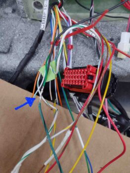
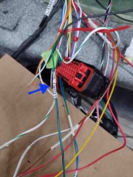
Here we have half of the RS-232 wire pair from the GRT EIS-4000 to the GRT HXr and Mini-X EFISs to display the engine info onto those displays. Since it is a RS-232 serial wire pair, before solder splicing wire #2 I twisted the second wire with this green one.
The majority of wires I finished connecting today were for the GRT EIS-4000, either to the panel or to the P9/P10 connectors, or the GRT MAP sensor (for power), but one circuit was simply an Ancillary Power feed from the panel to the one item currently on it: the D-Deck Fan Thermal Controller. This controller turns the D-Deck cooling and exhaust fans on at 85º F and off at 80º F. It’s actually more of computer type component, so it has a computer style power connector.
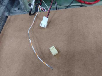
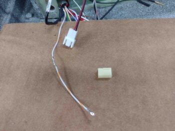
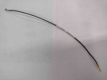
Here I’ve solder spliced on a segment of the same color 22 AWG wire (I try to maintain the same colors if possible) with a connector socket already crimped in place.
I then added a piece of heat shrink over the solder splice and covered that with my wire label.
A side note on my D-Deck wire labels: since I can pretty much see component A to component B I don’t strictly follow my wire labeling code as I do on the rest of this bird where I have a myriad of wires all running helter-skelter.
Here the Ancillary Power Wire is terminated into the Fan Thermal Controller power connector.
Of course our DC power circuits need positive (+) power and ground (-), so I made up the ground wire for the Fan Thermal Controller to plug into the connector, which I have the connector socket crimped onto one end of this wire. The other end is also terminated with a crimped pin for the D-Deck G6 Grounding Buss, which is a 9-pin D-Sub connector.
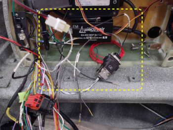
Here we have the Fan Thermal Controller ground wire terminated into the controller’s power connector on one end, and the D-Deck G6 Ground Buss in the center of the pic. Notice the unconnected ground wires coming from the G6 ground buss (center bottom of pic) that are terminated with a D-Sub socket for the P10 connector and a CPC socket for the P9 connector. Also, just below the G6 ground buss is the ground wire for the MAP sensors that will be terminated into the G6 ground buss once all the D-Deck components are installed.
I accounted for literally every wire coming into the D-Deck from the panel, hell hole or elsewhere and verified that the labeling was correct. If it wasn’t, I pulled the old label off and relabeled. Of course any changes, updates or discrepancies I annotated on my wiring diagrams and/or connector pinout sheets. Tomorrow I’ll spend a little bit of time wrangling the wires to get them organized and looking nice, and then won’t really deal with the D-Deck components & wiring again until final engine install.
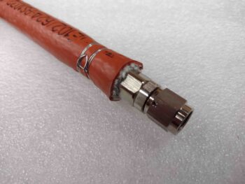
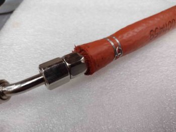
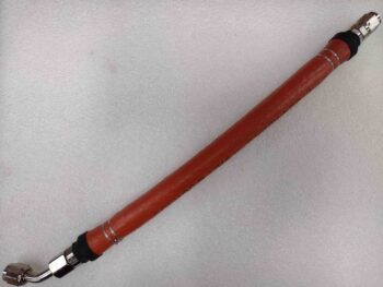
My last task of the evening was using my Clamptite tool to secure the orange fire sleeve to the FI Servo to Fuel Flow Divider (aka spider) -4 hose (left pic). I then added red hi-temp RTV to seal the end of the fire sleeve to the hose (right pic).
I think some folks roll their hose up under itself on the end, which looks nice, although after a quick search on the web I couldn’t find any how-to’s on doing that… No worries, I just went to my ol’ standby of cleaning up the red RTV gooped up ends by covering the seam with a band of heat shrink, which is nothing really more than cosmetic.
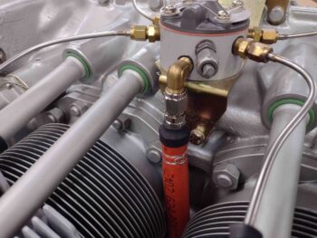
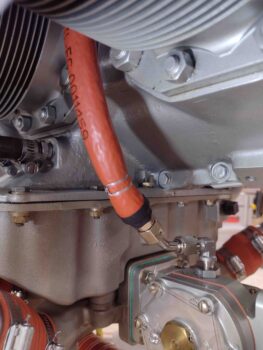
I then reinstalled the hose to check out how it fits and looks. Here’s the top side connection with the fuel spider.
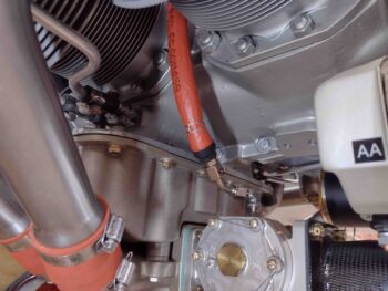
And the bottom side connection to the FI Servo outlet fitting.
I’ll note this isn’t the final install for this hose, just a quick visual and clearance check. Here we have a bit closer shot.
And with that, I called it a night. Tomorrow I should receive my other 120º -6 hose end fittings and plan on making up the mechanical fuel pump to FI servo fuel feed hose. I’ve also started the process to figure out and order my throttle and mixture cables prior to removing the engine —to finalize the forward/accessory case configuration and component installs.

