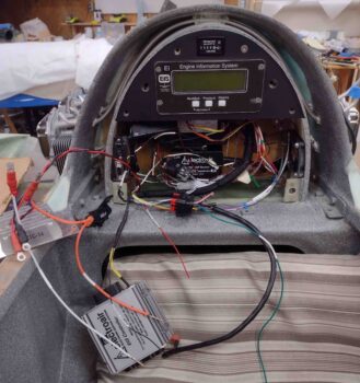
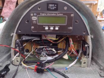
The good news is that I got the D-Deck/GIB headrest engine components wiring pretty much completely finished, including wrangling all the wires so that they are organized and look fairly decent.
Here’s a closer shot… the only wires remaining that need to be hooked up are the 5 wires from the Electroair coil pack that sits on the upper firewall. These wires can’t be finalized until after the firewall covering is put into place.
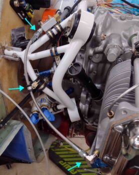
I received a couple of order shipments from Summit Racing, one had the 14″ -3 AN stainless steel hose to connect the MAP Manifold block to the #3 cylinder. After testing the fit and confirming the hose length was good, I installed back-to-back Adel clamps to secure the hose to the engine mount.
I then gooped up the threads on the 90º -3 AN tube x 1/8″ NPT fitting and torqued it into place on the #3 cylinder. Finally, I secured the hose ends to each fitting, torquing them to spec as well.
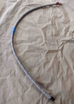
As I’m sure you’ve obviously seen, I roll my own fuel and oil hoses… so I figured I would show how I make one of them.
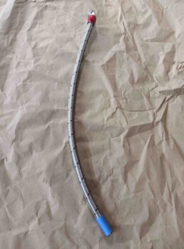
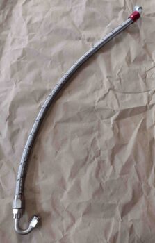
After previously attaching a 90º hose end to a length of -6 stainless steel hose, I then attached it to the fuel pump. I then ran it through an Adel clamp and to the fuel servo to determine a good length and then marked the hose for cutting. Pic #2 shows the hose cut to length using a Dremel tool with a cutoff disk.
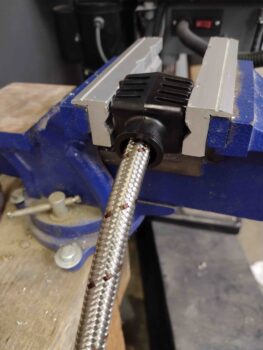
I have a nifty Kool Tools device that allows me to simply install the hose end cap into the tool block and then secure the block in the vise. I then simply insert and twist the cut hose end with a good little bit of pressure into the captured hose end cap and within 10 seconds it’s seated and ready for the next step.
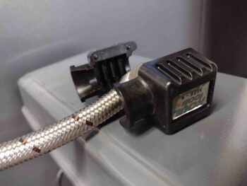
Here’s the Kool Tools block apart with the seated hose into the hose end cap. This tool is obviously very handy and I’ll say the only glaring issue with it is that I DON’T have one for the -4 size hoses, so I have to hand-jam all those hoses into the hose end caps (read: punctured fingers nearly every time!).
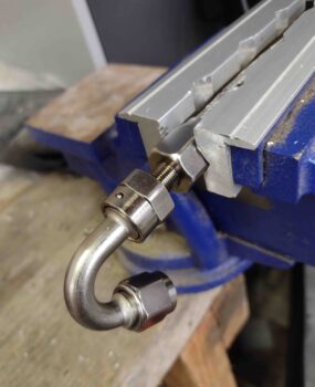
On a straight hose end fitting normally I’ll mount the threaded barb in the vise facing out and press the hose end cap & hose firmly onto the threaded hose end to start the final install step. But when the hose end has a distinct curve it often won’t fit in the soft jaws made for hose end installations, so the process is completed in reverse from above. Sometimes this is a real pain, other times —like here— it’s not too bad.
And Voila! A new -6 fuel hose.
Now, the very possible irony of me showing how I made my “final” fuel hose is that it may very well not be the final fuel hose that I make. I ran downtown to run some errands, get a haircut, and get some more short brass 4-40 screws for the GRT EIS-4000 D-Sub connectors (and to find a hex head screw to replace one of the slotted screws on the P-MAG wire plug to allow much easier install/removal with the fuel pump in the way). Upon returning home as I awaited Jess’s arrival for dinner, I continued my research regarding the throttle and mixture cable installs.
I guess as with much in this build, there are some things that I assume (yes, I know…), simply take for face value and honestly never think about until I’m staring them in the face. I obviously try to minimize those assumptions with as much prep and research as I can, but there are a good number of things (clearly) that fall through the cracks. My upcoming throttle and mixture cables, and how they interface with the fuel injection servo, are unfortunately and very possibly now in this category.
What am I on about? During my info gathering on the throttle and mixture cables, I ran across a page about 10 pages into the California Push-Pull catalog… behind all the technical info on cable nomenclature, sizes, determining install lengths, etc. which is where my focus has been both now and the cursory info I reviewed in the past.
The title of this page is “Control Cable Cautions and Warnings” and caution #5 caught my eye, specifically because my install is simply opposite of what they say to “Always” do . . .
I’m not trying to be melodramatic here, but on the eve of prepping to start working my exhaust pipe issues in earnest, and having thought my fuel injection servo air induction and fuel hose routing was in the bag —and I just needed to slap in some cables to have it off the plate— I may very well be going back to square one for the proverbial third times a charm thing.
As a crosscheck, I went to Cablecraft’s website and here’s what they had to say:
“Working loads should be highest in the pull direction. In the compression mode the loads need to be specified at 50% of the pull load unless using Armored Core which will yield a higher compression to tension ratio.”
Yep, I totally missed this requirement.
I’ll call both California Push-Pull and Cablecraft tomorrow to see what options I have and what my play needs to be in regards to this. Again, I’m a little in the dark here because everyone I know has the standard forward-facing servo that allows cables to come into the engine compartment, loop around from the back side so that the cables are actually facing forward and organically meeting this requirement that I’m just discovering. With my aft-facing servo I clearly and simply don’t have the option (or the physical space) to do that type of install.
To get ahead of this I brushed off my COA 2 Powerpoint slide deck and created a new COA X to capture possible requirements and to get an idea of the workload involved in meeting this “new” requirement. What I determined after going through this process was 2 primary tasks would have to be accomplished:
- The throttle quadrant would have to be converted to a reverse configuration (move pivot point to mid-lever vs current pivot point at bottom of lever).
- Invert the fuel injection servo 180º from it’s current installed position.
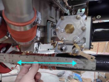
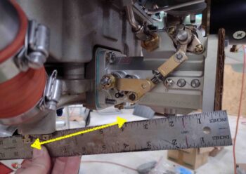
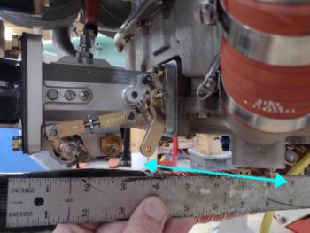
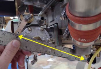
After determining WHAT would most likely need to be done, I then needed to do a recon to determine HOW (or even IF) it could be done. I started by grabbing pics of the general axes the cable ends would need to move to actuate the servo levers.
Here we have the mixture lever on the current left side. Note that it is situated towards the aft end of the servo and would pivot below the servo.
With the servo inverted, we now have the throttle lever on the left side. Note that it is situated towards the forward end of the servo at about mid-elevation, and would also pivot below the servo.
On the right side in the current servo configuration, the throttle mixture is pretty much a mirror image as it would be on the left side… situated towards the front of the servo, mid-elevation and would pivot below the servo.
The most pronounced configuration change would be with the mixture lever on the right side: its aft position would remain the same obviously, but its pivot distance is a bit further away (not saying this is a negative, just noteworthy).
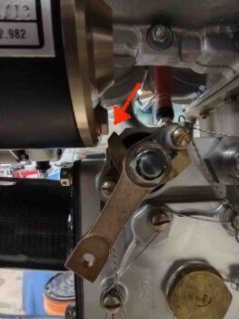
I’ll note 2 more characteristics of having the fuel injection servo installed in this position: First, I had to remove the starter in order to mount the servo, there’s that little clearance initially, and not a whole lot after mounting either (see below)… but enough (from what I can tell so far). Second, the routing of the fuel hose to the servo will either be much more circuitous if from below, or would have to go above the cold air induction pipes… more data required for a final call on this.
Here’s a shot of the tight clearance between the fuel injection servo, specifically the mixture lever arm assembly, and the aft edge of the starter. About 1/8″ I’d guesstimate.
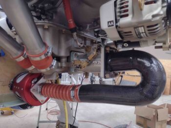
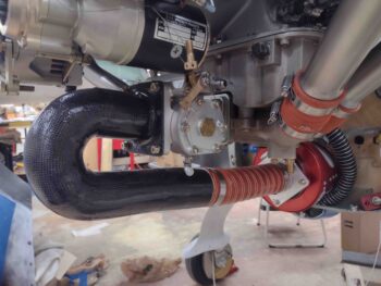
While I’d of course prefer to find a solution that doesn’t send me back to square one on the servo installation, I have to admit the final look of the servo in this position is much cleaner given that the bulk of the servo sits high on the top in this configuration vs my current configuration.
Clearly what I was checking here was if and how the inverting of the fuel injection servo would impact the fit and clearance of the air induction tube. The fit is obviously fine, and at first swag it appears to be in the same position but I’ll need to mount the lower cowling just to ensure it has the same or better clearance.
Again, another very likely curve ball I’ll need to contend with… either in more work to remedy with reconfigurations, or more money to buy either a more robust or higher end cable capable of working effectively in both the push and pull directions. Obviously I’m not thrilled with this latest development, but will keep pressing forward and accept the inevitable time taxation that these esoteric builds seem to incur.

