
I quite often finalize these blog posts and proofread them the next morning from the day before’s activities, and then make up a task list for the day on what I would like to get accomplished… quite often a 2 cup of coffee process.
It was at the tail end of my morning routine when I got a call from Frank at California Push-Pull Cables, in Chico, California. I conveyed to him the situ with how my fuel injection servo is configured as compared to the industry’s specific comms regarding pull vs push directions for installing these cables. As I half expected, with the amount of force we’re talking about here on the Silver Hawk FI servo, there’s very little issue with reversing how it would optimally be installed.
In short, I got a green light to proceed with my current configuration from someone who is very knowledgeable in the industry, and I’ll add the go-to contact on cables for our RV-building cousins. We further discussed cables types, styles and the process to work out my ordering a set of cables.
I’m not surprised with what Frank said, and again, I half expected it. I debated on even mentioning it in yesterday’s blog write-up, but had I known of the requirement for emphasizing pull over push up front I could have at least prioritized that into my own configuration however best possible. Anybody else reading this blog now hopefully has a better understanding of this little important detail as well.
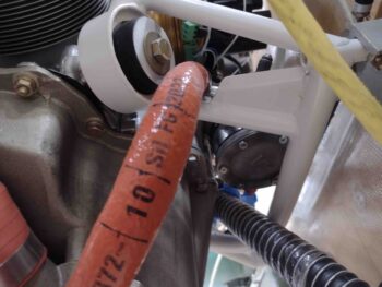
With that bit of good news in my back pocket, I proceeded to fire sleeve my -6 fuel hose by using my Clamptite tool to secure each end with safety wire. I then slathered up each opening edge with red RTV and covered it with a narrow piece of black heat shrink.
If you’re wondering why I didn’t pressure test it first, that is what is described with a highly technical term in the aircraft homebuilding world: brain fart. I realized as I was gooping up the first end with red RTV that I totally spaced out and forgot to pressure test the hose first before the fire sleeve. Much easier to do without the sleeve in place.
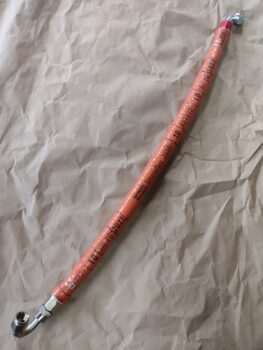
In my lack of experience with fire sleeve I hadn’t noticed before that it actually stretches. I had to go a size larger than I would normally when ordering this -6 sleeve since they were out of the “correct” size. I now realize I probably could have comfortably gone a size lower and still been totally fine… the things you learn on these builds.
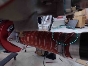
A very practical example of this was that instead of going through the hassle of pulling the blue fire sleeve off my firewall to fuel pump -6 fuel line, I simply added the orange fire sleeve right over top of the blue and it stretched a bit to cover it just fine. It was nice and tight so I just added a couple more rings of heat shrink, one on each end, and called it good. Upgrade complete.
As I was flipping the fuel injection servo back to its original configuration, I trimmed the SCEET tubing shorter by about a ring (1/4″ to 3/8″) to get it positioned forward on the air induction mounting tube flange. This resulted in what I hoped in that it let me pull the tubing a little tighter and allowed the tubing to flex on the mounting tube itself rather than just forward of the aluminum tube where it was forcing a slight crease in the SCEET tubing… the few degrees difference in my angle choice seems to be negated by mounting the SCEET tubing comparatively right at the edge of the aluminum tubing vs having the SCEET cover the entire aluminum tube and nearly touch the carbon fiber.
Just a point of note really, but anything that cleans up the air flow is good.
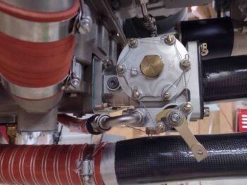
I had another component delivered today: my 90º -4 AN barbed fitting for the Sniffle Valve. I tried it out to check the clearance with the underlying SCEET tubing and it looks great. I changed the Sniffle Valve install because I wanted my configuration so that the Sniffle Valve was both vertical and the first component installed to be closest to the point of vacuum.
I’m confident gravity will still play its part even with this 90º fitting installed. I installed the fuel and oil resistant drain line to check out its fit on the barb… which required a bit of Simple Green to allow me to get the tubing on the barb.
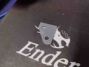
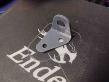
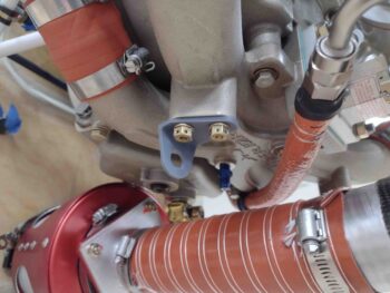
Notice the gray rectangular flat tabs bolted to the throttle and mixture cable mounting bosses on the underside of the cold air plenum in the pic above? These are tabs I 3D printed to check/verify the angle of the bolts on these bosses to allow for mounting the throttle and mixture cable brackets parallel to the aircraft centerline, or more specifically parallel to the servo throttle and mixture levers.
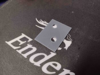
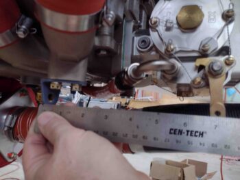
The scant literature I have on the Superior Cold Air Induction Plenum doesn’t note the bolt angles, and I guessed them to be at 30º. I was just a few degrees off in comparison to the throttle and mixture levers… note the clamped ruler to the mixture lever (not shown) in the pic below. It took a couple rounds for me to dial in the correct bolt angle for the test coupons to sit parallel when mounted to the plenum bosses.
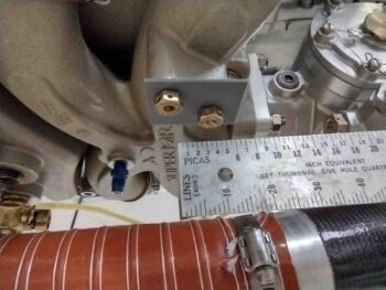
Once I got the initial rectangular bolt angle and spacing checking coupon aligned parallel, I focused on the travel distance of the cable end rod. I’ll need to verify my figures with Frank at Push-Pull, but for the mixture lever I calculated the rod end travel distance of 2.75″, and 3″ for the throttle lever.
In turn, these travel numbers translate into 7″ from cable attach point to the center of the lever travel on the mixture cable/lever and 7.38″ on the throttle cable/lever. With these dimensions in hand, I then made up a throttle-side test coupon measuring 3.75″ long. This length places the forward edge (opposite bolt holes) at 7.38″ from the hole center of the servo throttle lever at mid travel.
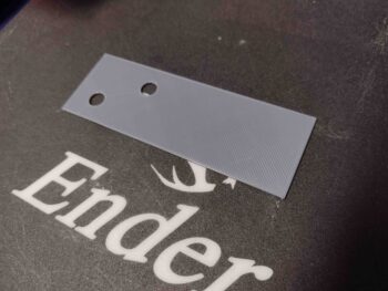
Back in Fusion 360 CAD I also trimmed down what will become the mounting bracket to match the bottom of the plenum boss to minimize excess mounting bracket material, and thus minimize weight. I’ll note that at this point these test coupons were 0.05″ thick and took about 10 minutes each to 3D print.
Here I’m checking the shape of the 3D printed test coupon that will become the 3D model for each respective throttle and mixture cable bracket. You can see there is a very slight overhang of the boss which I added back about 0.01″ to the edge on the next coupon.
I also transferred the shape of the plenum boss to the right side throttle cable bracket test coupon and test fitted it in place.
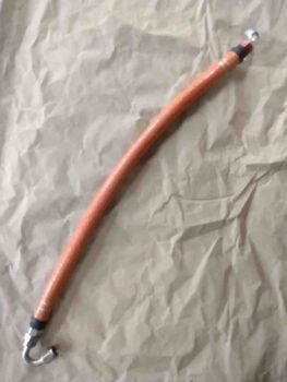
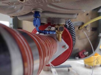
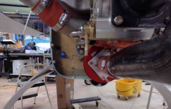
I then modeled up the actual left side mixture cable bracket in Fusion 360 CAD and 3D printed it. As it was printing I went ahead and installed the freshly fire-sleeved -6 fuel hose that feeds the fuel injection servo from the mechanical fuel pump. Currently I have one Adel clamp securing the hose in place, and may squeeze in another one later.
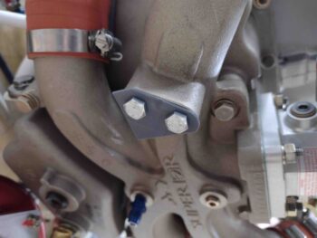
My biggest concern that I resolved —again, after all these years— is the clearance between this hose and the engine mount to allow good hose attachment to the fuel pump.
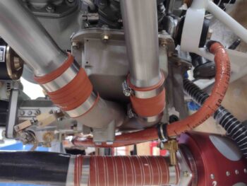
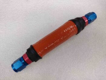
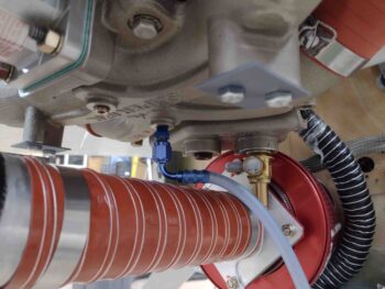
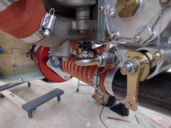
Again, pic #1 is a closer look at the clearance between this -6 fuel hose and the engine mount… very acceptable! Pic #2 shows the “120º” hose end fitting attach at the fuel injection servo. Actually, I’m very thankful for this odd duck 120º fitting since it allowed the best clearance of the four 120º hose ends that I tried out.
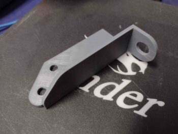
With the test install of the -6 fuel hose a success, I then went back into the house to retrieve my mixture cable mounting bracket 3D printed mockup.
It fits like a rock star so far . . .
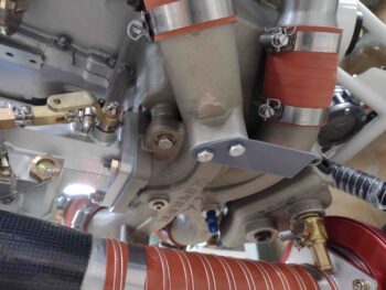
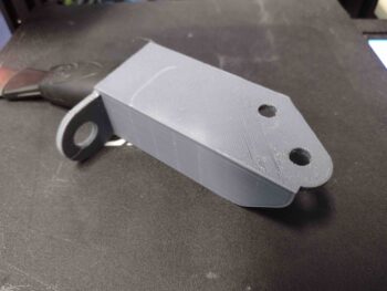
And 7″ from mounting bracket mid-point to the center of the servo mixture lever arm at mid travel (my hand slipped a hair while I was grabbing yet another fuzzy pic… this camera sucks).
Here we have the lateral left-right alignment to get the mixture cable mounted as straight on as possible with the fuel servo mixture lever attach point.
And a more downward shot of the mixture cable mounting bracket, -6 fuel line and servo mixture lever. Since the mixture bracket is fairly small, I’ll most likely make it out of 1/8″ 2024 aluminum angle.
As I was loading up the pics and prepping this post, “Bob” was whirring away making up the initial version of what will be the right side throttle cable bracket. Since this guy is cantilevered out a bit and requires a 90º right angled flange for the actual cable mount tab, I suspect it will be either steel or multiple bolted/riveted pieces of aluminum. Clearly the construction of this bracket will be more entailed than the mixture bracket.
Ok, yet another long day and late night, so time to pack it in. Tomorrow I’m helping out some friends with some handyman tasks so it will be a shortened airplane building day.