
As I mentioned yesterday, today was a short work day since I helped out my friends for a few hours with some home mechanical stuff. Between that, a Friday evening out, and problematic 3D prints of the throttle cable bracket mockup, I got even less done than I had planned on.
The tale of my throttle cable bracket variants reminds of Goldilocks and the 3 bears: #1 being “too small” with the first version too close to the -6 fuel hose. Plus the actual cable bracket mounting tab was vertical whereas it needs to be slightly angled up towards the aft side.
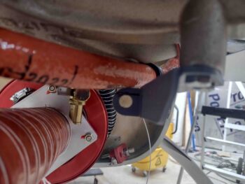
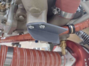
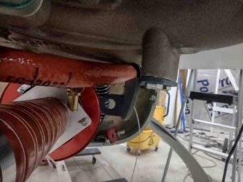
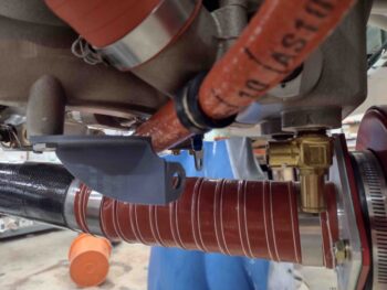
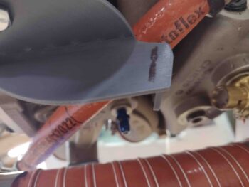
Here’s a couple more shots of the Version 1 throttle cable bracket that finished 3D printing late last night. Again, note the very slim clearance with the -6 fuel hose.
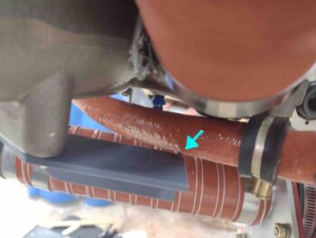
Well, continuing on with the Goldilocks theme: #2 was too big. That is the notched gap between the forward end of throttle cable bracket was a bit more than needed.
With the actual cable mounting tab just a hair lower than it needs to be, although on this version I angled it up facing aft just a bit. Still, the tab needed just a hair more angle upwards.
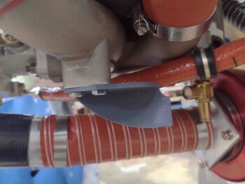
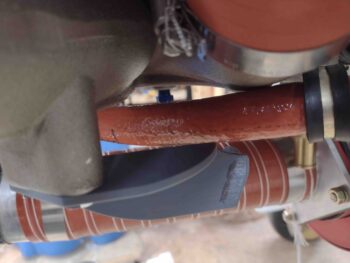
Version 3 is the closest to Goldilocks’ “just right”: the clearance with the hose isn’t too crazy big, although I will make it just a hair wider.
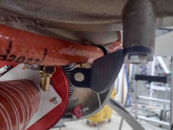
For the angle of the cable mount tab itself I kicked the bottom of it aft 1/8″. This actually resulted in too sharp of an angle so I’ll have to dial that back in.
Also, in increasing the angle of the mounting tab on the bracket, I lost track of my dimensions and ended up about 1/8″ forward of where the tab should be to provide a 7.38″ distance to the servo throttle lever at mid-pivot.
Regardless, this exercise is all academic at this point until I get more actionable data.
For example, I can’t determine actual dimensions until I pivot the servo throttle lever down/forward at least one notch. Having already moved the servo mixture lever, I was trying to keep from having to move the throttle lever as well. But this cable bracket mockup showed me that that the servo throttle lever must be repositioned. That in turn will drive changes in the dimensions for the bracket —a chicken vs egg endeavor— albeit I’m close enough in the ballpark with this bracket mockup to determine that the throttle lever must move forward.
That all being said, I still need to determine my actual cable rod end travel as well. Which again will drive dimensions on the throttle cable bracket. That will happen after at least one more discussion with Frank at Push-Pull cables on Monday.
For now though, I have enough information to know how to construct this thing and what material to order: I’ve determined that I’ll be using 1/8″ 2024 aluminum angle for both throttle and mixture cable brackets.
The actual cable mounting through-hole tab on the throttle cable bracket will be simply a piece of cut & drilled aluminum angle bolted (actually CS screws) to the main bracket structure. Simple and EZ-PZ. Plus it will provide an easier determination of getting the cable and end rod angles correct since I can thread the cable into the bracket’s cable tab BEFORE mounting it to the bracket structure, then just mark the cable/tab alignment on the bracket structure, disassemble, drill and CS screw the cable mounting tab to the bracket structure to finish it off.
My main goal tomorrow will be to ascertain the major lengths of the throttle and mixture cables, which I’ll then fine tune once I talk to Push-Pull. To find these lengths I’ll of course have to determine where the cables will transit the firewall, drill those holes, and also assess cable routes from engine to throttle quadrant.